Allied Telesis AT-CM301 Handleiding
Allied Telesis Netwerkkaart/adapter AT-CM301
Bekijk gratis de handleiding van Allied Telesis AT-CM301 (2 pagina’s), behorend tot de categorie Netwerkkaart/adapter. Deze gids werd als nuttig beoordeeld door 144 mensen en kreeg gemiddeld 4.2 sterren uit 9 reviews. Heb je een vraag over Allied Telesis AT-CM301 of wil je andere gebruikers van dit product iets vragen? Stel een vraag
Pagina 1/2
123
AT-CM301 and AT-CM302 Fast Ethernet
Media Converters Installation Guide
Overview
The AT-CM301 and AT-CM302 Media Converters are members of the Converteon family
of media converter products. They provide a simple and reliable way to connect Fast
Ethernet networks across distances of up to 2 kilometers (1.24 miles) using multimode
fiber optic cable. The products feature a 10/100Base-TX port and a 100Base-FX port.
The two cards support all of the same features, but they have different connectors on the
100Base-FX fiber optic ports. The features are listed here.
(* Requires the AT-CV5M02 Management Card.)
(** Requires an AT-CV5M02 Management Card in the upstream AT-CV5000 Chassis.)
Note
These line cards cannot be managed with the AT-CV5M01 Management Card.
613-001068 Rev. A
Converteon Enclosures
This product is supported in all four Converteon enclosures:
AT-CV5000 Chassis
AT-CV1203 Chassis
AT-CV1200 Chassis
AT-CV1000 Chassis
Related Documents
For background information on the Converteon product, refer to the Converteon AT-S73,
AT-S99, and AT-S102 Management Software User’s Guide, available from the Allied
Telesis web site.
Verifying the Package Contents
The following items should be in the shipping container:
One AT-CM301 or AT-CM302 Media Converter
This Installation Guide
Warranty card
If any item is missing or damaged, contact your Allied Telesis sales representative for
assistance. You should retain the original shipping material in case you need to return the
unit to Allied Telesis.
Reviewing Safety Precautions
Before installing the media converter, review the safety precautions detailed in the
Converteon chassis’ Installation Guide.
Twisted Pair Cable Specifications
The cable specifications for the 10/100Base-TX twisted pair port are listed here.
Fiber Optic Cable Specifications
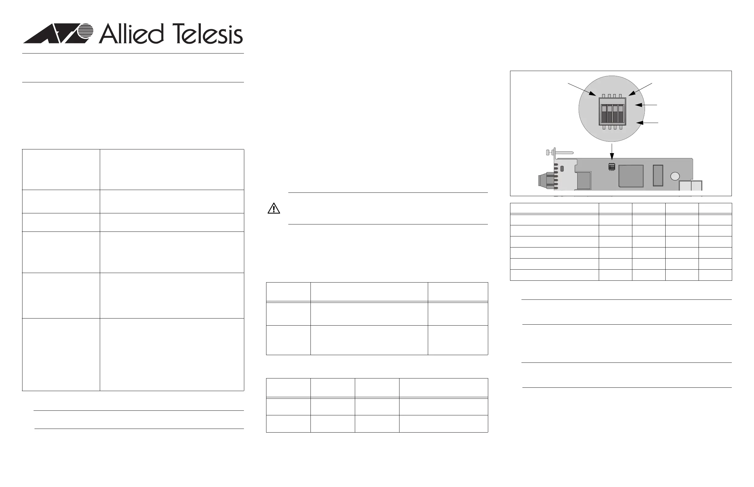
Setting the DIP Switches
The line card has DIP switches for setting the operating mode. You can also set the
operating mode with the optional AT-CV5M02 Management Card. To use the DIP
switches, refer to the figure and table. For background information on the operating
modes, refer to the Converteon AT-S73, AT-S99, and AT-S102 Management Software
User’s Guide.
Installing the Media Converter
Note
The media converter supports hot swapping and can be installed while the chassis
is powered on.
To install the media converter:
1.Remove the slot cover from one of the slots in the Converteon chassis by loosening
the captive screw with a Phillips head screwdriver. The unit can be installed in any of
the media converter slots.
Note
Retain the slot cover and reinstall it if you ever remove the card. An open slot allows
dust to enter the unit and reduces proper airflow in the chassis.
2.Align the edges of the line card with the guides in the slot and carefully slide the card
into the chassis until it is flush with the front of the chassis. Light pressure may be
needed to seat the module on the connector on the backplane in the chassis.
3.Secure the line card in the chassis by tightening the captive-screw with a Phillips
head screwdriver.
4.Remove the dust cover from the fiber optic port.
5.Connect the fiber optic cable to the fiber optic port.
6.Connect a twisted pair cable to the RJ-45 twisted pair port on the line card.
10/100Base-TX Twisted Pair
Port
IEEE 802.3u Auto-Negotiation
Half- or full-duplex mode
Auto-MDI/MDI-X
RJ-45 connector
IEEE 802.3x flow control at 10 or 100 Mbps
100Base-FX PortSupports distances up to 2 kilometers (1.24 miles) using
50/125 µm or 62.5/125 µm (core/cladding) multimode fiber
optic cable.
Fiber Optic Port ConnectorsAT-CM301 - duplex ST
AT-CM302 - duplex SC
Operating ModesLink Test
MissingLink
™
Smart MissingLink
The operating modes can be activated with or without support
for Operations, Administration, and Maintenance.
Operations, Administration, and
Maintenance (OAM) Features
Loopback tests*
Remote Converteon line card management*
Remote management software downloads*
Dying gasp**
Variable requests*
Other FeaturesJumbo frames up to 10,240 bytes
Ingress and egress packet rate limiting*
Operating mode and port status LEDs
Low power mode
Cyclical redundancy check
Suitable for managed and unmanaged network
environments
Management available with the AT-CV5M02 Management
Card
AT-S102 Management Software (preinstalled)
*613-001068 RevA*
Caution
The media converter line card is sensitive to and can be damaged by
electrostatic discharge. Wear a grounding device and observe electrostatic
discharge precautions when installing the card in the chassis.
SpeedCable Type
Maximum Operating
Distance
10 MbpsStandard TIA/EIA 568-B-compliant Category 3 or
better shielded or unshielded cabling with 100 ohm
impedance and a frequency of 16 MHz.
100 m (328 ft)
100 MbpsStandard TIA/EIA 568-A-compliant Category 5 or
TIA/EIA 568-B-compliant Enhanced Category 5
(Cat 5e) shielded or unshielded cabling with 100
ohm impedance and a frequency of 100 MHz.
100 m (328 ft)
Line CardConnector
Maximum
Distance
Fiber Optic Cable
AT-CM301Duplex ST2 km (1.24 mi.)50/125 µm or 62.5/125 µm (core/
cladding) multimode fiber optic cable
AT-CM302Duplex SC2 km (1.24 mi.)50/125 µm or 62.5/125 µm (core/
cladding) multimode fiber optic cable
Operating ModeSwitch 4Switch 3Switch 2Switch 1
Link Test (default setting)OffOffOffOff
MissingLinkOffOffOffOn
Smart MissingLinkOffOffOnOff
Link Test with OAMOffOnOffOff
MissingLink with OAMOffOnOffOn
Smart MissingLink with OAMOffOnOnOff
ON
1
43
2
OFF
14
SW1
1447
ON
1
432
OFF
14
SW1
1448
DIP Switch 1
Off
On
DIP Switch 4
Product specificaties
| Merk: | Allied Telesis |
| Categorie: | Netwerkkaart/adapter |
| Model: | AT-CM301 |
| Gewicht: | 113 g |
| Connectiviteitstechnologie: | Bedraad |
| Certificering: | FCC class A, EN55022 class A, VCCI class A, C-Tick, CE, EN55024, UL60950-1 (cULUS), EN60950-1 (TUV), \nEN60825, UL60950-1 (cULus), EN60950-1 (TUV), \nCAN/CSA C22.2 |
| Temperatuur bij opslag: | -25 - 70 °C |
| Golflengte: | 1310 nm |
| Luchtvochtigheid bij opslag: | 5 - 95 procent |
| Mean time between failures (MTBF): | 1500000 uur |
| Maximale overdrachtssnelheid van gegevens: | 1000 Mbit/s |
| Afmetingen (B x D x H): | 22 x 73 x 130 mm |
| Stroomverbruik (typisch): | 5.5 W |
| Bedrijfstemperatuur (T-T): | 0 - 40 °C |
Heb je hulp nodig?
Als je hulp nodig hebt met Allied Telesis AT-CM301 stel dan hieronder een vraag en andere gebruikers zullen je antwoorden
Handleiding Netwerkkaart/adapter Allied Telesis

18 Februari 2024
18 Februari 2024
18 Februari 2024
18 Februari 2024
18 Februari 2024
18 Februari 2024
18 Februari 2024
18 Februari 2024
18 Februari 2024
18 Februari 2024
Handleiding Netwerkkaart/adapter
Nieuwste handleidingen voor Netwerkkaart/adapter
8 Juli 2026
8 Juli 2026
8 Juli 2026
23 Juni 2026
23 Juni 2026
23 Juni 2026
22 Juni 2026
22 Juni 2026
18 Mei 2026
12 Mei 2026