Advantech PCM-3641 Handleiding
Advantech
Niet gecategoriseerd
PCM-3641
Bekijk gratis de handleiding van Advantech PCM-3641 (11 pagina’s), behorend tot de categorie Niet gecategoriseerd. Deze gids werd als nuttig beoordeeld door 2 mensen en kreeg gemiddeld 4.4 sterren uit 1.5 reviews. Heb je een vraag over Advantech PCM-3641 of wil je andere gebruikers van dit product iets vragen? Stel een vraag
Pagina 1/11

PCM-3641PCM-3641
PCM-3641PCM-3641
PCM-3641
4-por4-por
4-por4-por
4-por
t RS-232 High-Speed Modulet RS-232 High-Speed Module
t RS-232 High-Speed Module
PC/104 and the PC/104 logo are trademarks of the PC/104 Consortium Part no. 2000364100 1st Edition Printed in Taiwan August 2000
PCM-3641 4-port RS-232 High-Speed Module
Introduction
The PCM-3641 is a PC/104-compatible 4-port High-Speed
RS-232 serial interface module. It works with PC/104 CPU
modules or CPU cards which accept PC/104 expansion
modules. It provides four independent serial interfaces,
accessed through male DB-9 connectors.
The module’s industry-standard 16C550 asynchronous
communication chip is fully programmable. The module
requires no special commands or control codes if you use
the standard COM1 ~ COM4 port addresses.
Features
•Four independent RS-232 serial ports
•Transmission speeds up to 460 Kbps
•Independent/Shared IRQ settings for each of 4 serial
ports
•Wide IRQ selection: 3, 4, 5, 6, 7, 9, 10, 11, 12, 15
•Supports Standard DOS COM1, COM2, COM3, and
COM4
•Supports DOS/Windows 3.1 (PC-ComLib), Windows 95/
98/NT
•LED indicators: TX, RX
•Compatible with standard PC ports: COM1, COM2,
COM3, COM4
•On-board interrupt status register for greater throughput
•Complete RS-232 Modem-control signals
Specification:
•Bus interface: ISA
•Number of ports: 4
•I/O address: 0x0200 ~ 0x03F8
•IRQ: 3, 4, 5, 6, 7, 9, 10, 11, 12, 15
•Data bits: 5, 6, 7, 8
•Stop bits: 1, 1.5, 2
•Parity: none, even, odd
•Speed (bps): 50 ~ 460 K
•Connectors: Four DB-9 male
•Data signals: TxD, RxD, RTS, CTS, DTR, DSR, DCD, RI,
GND
•Power requirement: +5V@200 mA (Typical) ;
+5V@ 250 mA (Max.)
•Clock input: 14.7456 MHz
•Operating Temperature.: 0 ~ 65° C (refer to IEC-
68-1-1, 2)
•Storage Temperature: -25 ~ 80° C
Initial inspection
We carefully inspected the PCM-3641 both
mechanically and electrically before we shipped it.
It should be free of marks and scratches and in
perfect electrical order on receipt.
Handle the board only by its edges. The static
charge on your body may damage its integrated
circuits. Keep the card in its anti-static package
whenever it is not installed. You can use this
package to return the card if it should need repair.
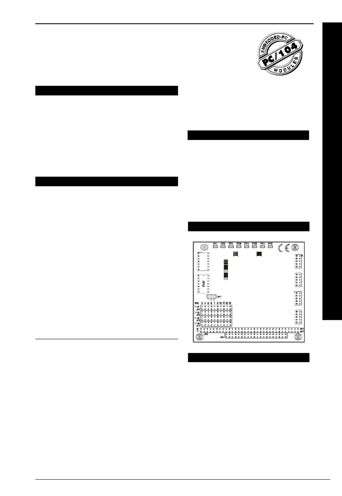
Board Layout
A4
A5
A6
A7
A8
MODE 1
SPEED
A3
A4
A5
A6
A7
A8
MODE 0
D1
+ + + ++ + + +
D2
D3
D4 D5 D6 D7 D8
MODE0:
MODE1:
ON-Standard
OFF-Enhance
ON-SHARE IRQ
OFF-Indep IRQ
SPEED: ON-8X
OFF-1X
R3
RP1
RP2
RP4
RP5
JP7 CH/1
JP7 CH/2
JP7 CH/3
JP7 CH/4
RP3
R4
VECTOR ADDRESS BASE ADDRESSSW1SW2
PCM-3641 REV. A1 01-1 4 PORT RS-232
Card Conguration
Each port on the PCM-3641 card has jumpers and
2 DIP switches which require configuring prior to
use. The DIP switches set the port to the
appropriate I/O address and different modes. The
jumpers set the port’s IRQ.

2PCM-3641 User's Manual
ONON
ONON
ON
A3
A4
A5
A6
A7
A8
MODE 0
Default Settings
The board is shipped with default settings. If you need to
change these settings, however, see the following sections.
Otherwise, you can simply install the card.
PCM-3641 Default Configuration
Setting Default Function
JP1 IRQ 5
Speed Mode 1 x
IRQ mode Share
Base Address Address 300H
Vector Address Interrupt 280H
Standard/ Enhanced Enhance
Operating System Windows 95/98/NT
Jumper and switch settings
The PCM-3641 can function in many different modes
according to your application needs. These modes include
Standard/Enhance Mode, Independent/Shared IRQ Mode,
Speed Mode and Operating System Mode. Details of these
specific modes are described as follows:
Standard/Enhanced Mode (MODE0)
The PCM-3641 can be used in standard or enhanced
mode. In standard mode the I/O addresses are compatible
with the standard PC communication ports, COM1~COM4.
In enhanced mode you can select a different base address.
The offset of each port from the base address is fixed. You
can use MODE0 of DIP switch SW1 to select standard or
enhanced mode.
Standard mode
In standard mode, the I/O address of the ports are as
follows:
Port I/O address Interrupt No.
Port 1 3F8 Selectable
Port 2 2F8 Selectable
Port 3 3E8 Selectable
Port 4 2E8 Selectable
Enhanced mode
SW1
In enhanced mode, you can select a different base address.
The base address determines the address for each of the
four ports.
The I/O addresses for the four ports are as follows:
Port I/O address
Port 1 Base + 00H
Port 2 Base + 08H
Port 3 Base + 10H
Port 4 Base + 18H
You use switches 1~6 of DIP switch SW1, a 7-position DIP
switch, to set the base address. You can set the base
address anywhere from hex 200 to 3F8.
To set the base address, you have to calculate the base
address as follows:
Note: On the PCM-3641 the address line A9 does not
appear on the DIP switch as it is permanently hard-
wired to HEX 200 on the card.
The following table shows different base address settings.
Port base address (SW1)
Base Address A3 A4 A5 A6 A7 A8
200 - 207 l l l l l l
208 - 20F ¡ l l l l l
*300 - 307 l l l l l ¡
3E8 - 3EF ¡ l ¡ ¡ ¡ ¡
3F8 - 3FF ¡ ¡ ¡ ¡ ¡ ¡
l: ON ¡: OFF * : Default
Note: If your CPU module or card has serial interface
ports, you will need to adjust the I/O port addresses
(or disable the ports) to avoid conflicts.
Independent/Shared IRQ mode
(MODE1, JP1, JP2, JP3, JP4)
The card’s IRQ can be set up using MODE1 of SW2.
Please note that the DIP switch is for setting the mode as
shown below.
ONON
ONON
ON
A3
A4
A5
A6
A7
A8
MODE 0
SW1
ONON
ONON
ON
A3
A4
A5
A6
A7
A8
Base address Decimal HEX
line value value
A3 8 8
A4 16 10
A5 32 20
A6 64 40
A7 128 80
A8 256 100
A9 512 200

3PCM-3641 User's Manual
Shared IRQ Mode
Independent IRQ Mode
Independent IRQ Mode (JP1-JP4)
In this mode, each of the four ports can have IRQ channels
set individually. For each port, select an IRQ which is not
already in use by another card in the system. The map of
jumpers and ports is shown below.
Port 1 —> JP1
Port 2 —> JP2
Port 3 —> JP3
Port 4 —> JP4
Shared IRQ Mode (JP1)
Select an IRQ which is not already in use by another card
in the system. If you are installing more than one PCM-
3641, set them to different IRQ numbers. Jumper Bank JP1
controls the card IRQ. Simply place the jumper on the
required interrupt level as shown in the following figure.
Interrupt Status Register Setup (SW2, Vector
address)
This feature on the PCM-3641 is utilized in the shared IRQ
mode. When data arrives at one of the four ports, it will
generate an interrupt in the interrupt register. The PC
software can read this, and identify immediately which port
generated the interrupt. This saves time, and makes
programming easier. When a data bit of the interrupt status
register is set to 0, the corresponding channel is selected to
generate an interrupt. If the bit is 1, then no interrupt is
generated. DIP switch SW2 controls the card’s interrupt
status register, as shown in the following figure and table.
3 4 5 6 7 9 10 11 12 15
JP1
Interrupt Status Register SW2
Bit Function
0 Port 1
1 Port 2
2 Port 3
3 Port 4
4 Not Used
5 Not Used
6 Not Used
7 Not Used
The user may change the interrupt status address via SW2.
Please note that the address decoder will occupy a
continuous, 16-byte area related to the switch setting. For
example, if you set the switch to 210H, then the address
210H to 21FH will all be decoded. The various DIP switch
settings (SW2) for the interrupt status register are as shown
in the table opposite.
A4 A5 A6 A7 A8
Interrupt
Register
ON ON ON ON ON 200H
OFF ON ON ON ON 210H
ON OFF ON ON ON 220H
OFF OFF ON ON ON 230H
ON ON OFF ON ON 240H
OFF ON OFF ON ON 250H
ON OFF OFF ON ON 260H
OFF OFF OFF ON ON 270H
ON ON ON OFF ON 280H
OFF ON ON OFF ON 290H
ON OFF ON OFF ON 2A0H
OFF OFF ON OFF ON 2B0H
ON ON OFF OFF ON 2C0H
OFF ON OFF OFF ON 2D0H
ON OFF OFF OFF ON 2E0H
OFF OFF OFF OFF ON 2F0H
ON ON ON ON OFF 300H
OFF ON ON ON OFF 310H
ON OFF ON ON OFF 320H
OFF OFF ON ON OFF 330H
ON ON OFF ON OFF 340H
OFF ON OFF ON OFF 350H
ON OFF OFF ON OFF 360H
OFF OFF OFF ON OFF 370H
ON ON ON OFF OFF 380H
OFF ON ON OFF OFF 390H
ON OFF ON OFF OFF 3A0H
OFF OFF ON OFF OFF 3B0H
ON ON OFF OFF OFF 3C0H
OFF ON OFF OFF OFF 3D0H
ON OFF OFF OFF OFF 3E0H
OFF OFF OFF OFF OFF 3F0H
ONON
ONON
ON
A4
A5
A6
A7
A8
MODE 1
SPEED
SW2
ONON
ONON
ON
A4
A5
A6
A7
A8
MODE 1
SPEED
SW2
ONON
ONON
ON
A4
A5
A6
A7
A8
MODE 1
SPEED
SW2
Product specificaties
Merk: | Advantech |
Categorie: | Niet gecategoriseerd |
Model: | PCM-3641 |
Heb je hulp nodig?
Als je hulp nodig hebt met Advantech PCM-3641 stel dan hieronder een vraag en andere gebruikers zullen je antwoorden
Handleiding Niet gecategoriseerd Advantech
30 Juli 2025
30 Juli 2025
30 Juli 2025
30 Juli 2025
30 Juli 2025
30 Juli 2025
30 Juli 2025
30 Juli 2025
30 Juli 2025
30 Juli 2025
Handleiding Niet gecategoriseerd
- Creality3D
- D-Jix
- Truma
- Earthwise
- Loewe
- SAUTVS
- Sabo
- GFM
- Neunaber
- AudioQuest
- Dreambaby
- Baccarat
- Urbanista
- Benidub
- Nicai Systems
Nieuwste handleidingen voor Niet gecategoriseerd
30 Juli 2025
30 Juli 2025
30 Juli 2025
30 Juli 2025
30 Juli 2025
30 Juli 2025
30 Juli 2025
30 Juli 2025
30 Juli 2025
30 Juli 2025