Advantech PCM-3614 Handleiding


Bekijk gratis de handleiding van Advantech PCM-3614 (6 pagina’s), behorend tot de categorie Niet gecategoriseerd. Deze gids werd als nuttig beoordeeld door 4 mensen en kreeg gemiddeld 4.8 sterren uit 2.5 reviews. Heb je een vraag over Advantech PCM-3614 of wil je andere gebruikers van dit product iets vragen? Stel een vraag

Pagina 1/6
PCM-3614
4-port RS-422/485 High-Speed Module
PC/104 and the PC/104 logo are trademarks of the PC/104 Consortium Part no. 2000364100 1st Edition Printed in Taiwan August 2000
PCM-3614 4-port RS-422/485 High-Speed Module
Introduction
The PCM-3614 is a PC/104-compatible module with four in-
dividually configurable RS-422/485 ports. It works with PC/
104 CPU modules to extend additional RS-422/485 ports. The
PCM-3614 also features lots of functions such as high trans-
mission speed 921.6 kbps, independent/shared IRQ and more.
It also provides high-performance 16C550 UART communi-
cation chip with 16-byte FIFO to reduce CPU load. This makes
the PCM-3614 especially suitable for multitasking environ-
The PCM-3614 comes with a Windows 95/98/NT/ME con-
figuration utility (Windows 2000/XP utility will soon be ready
and allowed to download through our Web site). The Win-
dows configuration utility provides functions such as self-di-
agnostics and performance analysis for easy troubleshooting
and debugging.
The PCM-3614 provides versatile function settings to meet
users' needs. These function settings include Standard/En-
hance mode, Independent/Shared IRQ mode and Speed
mode. Standard/Enhance mode setting helps the user use
base address more flexible. Especially in Enhance mode, dif-
ferent base addresses can be set according to the applica-
tion. In Shared IRQ mode, all ports of interrupt can be speci-
fied to one. This solves the problem of IRQ insufficiency within
the embedded system. In Speed mode, the PCM-3614 al-
lows transmission rate up to 921.6 kbps, improving the over-
all performance of the system.
Features
Four Independent RS-422/485 serial ports
Automatic RS-485 data flow control
Transmission speeds up to 921.6 Kbps
Shared IRQ settings for each port
Windows configuration utility for Windows 95/98/NT/ME
P.S. Windows 2000/XP/CE driver will soon be available on
our Web site
Built-in termination resistors
LED indicators: TX, RX
Standard PC ports: COM1, COM2, COM3, COM4
compatible
Specification
Bus interface: PC/104 (ISA)
Number of ports: 4
I/O address: 0x000 ~ 0x3F8
UART: 4 x 16C550
IRQ: 3, 4, 5, 6, 7, 9, 10, 11, 12, 15
Data bits: 5, 6, 7, 8
Stop bits: 1, 1.5, 2
Parity: none, even, odd
Speed (bps): 50 ~ 921.6K
Connectors: Four DB-9 male
Signal support: TxD+, TxD-, RxD-, CTS+, CTS-,
RTS+ and RTS-
Surge protection: 1000 V
DC
Temperature:Operating : 0 ~ 65° C
(refer to IEC-68-1-1,2) ( 32~149° F)
Storage : -25 ~ 80° C (-13~176° F)
Operation Humidity: 0% ~ 90% Relative
Humidity, non-condensing
Product Package
PCM-3614 PC/104 4-port RS-422/485 High-
Speed Module
Advantech ICOM Driver/Utility CD
One cable
Initial inspection
We carefully inspected the PCM-3614 both mechani-
cally and electrically before we shipped it. It should
be free of marks and scratches and in perfect elec-
trical order on receipt.
Handle the board only by its edges. The static change
on your body may damage its integrated circuits.
Keep the card in its anti-static package whenever it
is not installed. You can use this package to return
the card if it should need repair.
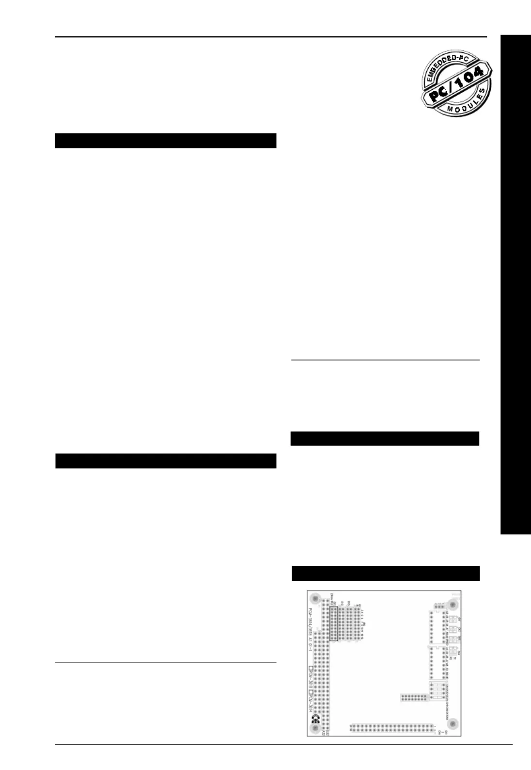
Board Layout
2PCM-3614 User's Manual
Card Configuration
Each port on the PCM-3614 card requires configuration prior
to use. The DIP switches set ports to the appropriate I/O ad-
dress (SW2) and different modes (SW1). The jumpers set the
port's IRQ.
Default Settings
The board is shipped with default settings. If you need to
change these settings, however, see the following sections.
Otherwise, you can simply install the card.
PCM-3614 Default Configuration
Setting Default Function
JP3 IRQ 5
Speed Mode 1 x
IRQ mode Share
Base Address Address 300H
Vector Address Interrupt 280H
Standard/ Enhanced Enhance
Operating System Windows 95/98/NT
Jumper and switch settings
The PCM-3614 can function in many different modes accord-
ing to your application needs. These modes include Standard/
Enhanced Mode, Independent/Shared IRQ Mode, Speed
Mode, and Operating System Mode. Details of these specific
modes are described as follows:
Standard/Enhanced Mode (M0)
PCM-3614 can be used in standard or enhanced mode. In
standard mode the I/O addresses are compatible with the
standard PC communication ports, COM1 ~ COM4. In en-
hanced mode you can select a different base address. The
offset of each port from the base address is fixed. You can
use M0 of DIP switch (SW1) to select standard or enhanced
mode.
In the following sections, we will use the icons shown below
to represent switches set for ON or OFF.
Standard mode
In standard mode, the I/O address of the ports are as follows:
Port I/O address Interrupt No.
Port 1 3F8 Selectable
Port 2 2F8 Selectable
Port 3 3E8 Selectable
Port 4 2E8 Selectable
Enhanced mode
In enhanced mode, you can select a different base address.
The address dete mines the address or each of thebase r f
four ports.
The I/O addresses for the four ports are as follows:
Port I/O address
Port 1 Base + 00H
Port 2 Base + 08H
Port 3 Base + 10H
Port 4 Base + 18H
You use switches 1~7 of DIP switch SW2 to set the base
address anywhere from hex 200 to 3F8.
To set the base address, you have to calculate the base
address as follows: (switch ON is 0, switch OFF is 1.)
The following table shows different base address settings.
Port base address (SW2)
Base Address A3 A4 A5 A6 A7 A8 A9
200 - 207 (hex) llllll¡
208 - 20F (hex) ¡lllll¡
*300 - 307 (hex) lllll¡¡
3E8 - 3EF (hex) ¡l ¡¡¡¡¡
3F8 - 3FF (hex) ¡¡¡¡¡¡¡
l ¡: ON : OFF * : Default
Note: If your CPU module or card has serial interface ports,
you will need to adjust the I/O port addresses (or dis-
able the ports) to avoid conflicts.
Switch is set ON.
Switch is set OFF.
ONON
ONON
ON
A 4
A 5
A 6
A 7
A 8
SW1
A 9
M0
M1
ONON
ONON
ON
A 4
A 5
A 6
A 7
A 8
SW1
A 9
M0
M1
ONON
ONON
ON
A 3
A 4
A 5
A 6
A 7
A 8
Base address Decimal HEX
line value value
A3 8 8
A4 16 10
A5 32 20
A6 64 40
A7 128 80
A8 256 100
A9 512 200
A 9
SPEED
3PCM-3614 User's Manual
SW1
ONON
ONON
ON
A 4
A 5
A 6
A 7
A 8
A 9
M0
M1
Independent/Shared IRQ mode
(M1, JP3, JP4, JP6, JP7)
The cards IRQ can be set using M1 of SW1. Please note that
the DIP switch is for setting the mode as shown below.
Shared IRQ Mode
Independent IRQ Mode
Independent IRQ (JP1-JP4)
In this mode, each of the four ports can have IRQ channels
set individually. For each port, select an IRQ not in use by
other devices in the system. The map of jumpers and ports is
shown below.
Port 1 > JP3
Port 2 > JP4
Port 3 > JP5
Port 4 > JP6
Shared IRQ (JP3)
Select an IRQ which is not in use by another card in the sys-
tem. If you are installing more than one PCM-3614, set them
to different IRQ numbers. Jumper Bank JP3 controls the card
IRQ. Please refer to the following figure for example.
Interrupt Status Register Setup (SW1, Vector
address)
The feature on the PCM-3614 is utilized in the shared IRQ
mode. When data arrives at any one of the four ports, an in-
terrupt will be generated in the interrupt register. The PC soft-
ware can read this, and identify immediately which port gen-
erated the interrupt. This saves time and makes programming
easier. When a data bit of the interrupt status register is set to
0, the corresponding channel is selected to generate an in-
terrupt. If the bit is 1, then no interrupt is generated. The DIP
switch, SW1, controls the cards interrupt status register, as
shown in the following figure and table.
Interrupt Status Register SW1
Bit Function
0 Port 1
1 Port 2
2 Port 3
3 Port 4
4 Not Used
5 Not Used
6 Not Used
7 Not Used
The user may change the interrupt status address via SW1.
Please note that the address decoder will occupy a continu-
ous, 16-byte area, according to the switch setting. For exam-
ple, if you set the switch to 210H, then the address 210H to
21FH will be decoded. The various DIP switch settings (SW1)
for the interrupt status register are shown in the table below.
3 4 5 6 7 9 10 11 12 15
JP3
SW1
ONON
ONON
ON
A 4
A 5
A 6
A 7
A 8
A 9
M0
M1
A 9
M0
M1
SW1
ONON
ONON
ON
A 4
A 5
A 6
A 7
A 8
A4 A5 A6 A7 A8 A9
Interrupt
Register
ON ON ON ON ON ON 000H
OFF ON ON ON ON ON 010H
ON OFF ON ON ON ON 020H
OFF
OFF ON ON ON ON 030H
ON ON OFF ON ON ON 040H
OFF ON OFF ON ON ON 050H
ON OFF OFF ON ON ON 060H
OFF OFF OFF ON ON ON 070H
ON ON ON OFF ON ON 080H
OFF ON ON OFF ON ON 090H
ON OFF ON OFF ON ON 0A0H
OFF OFF ON OFF ON ON 0B0H
ON ON OFF OFF ON ON 0C0H
OFF ON OFF OFF ON ON 0D0H
ON OFF OFF OFF ON ON 0E0H
OFF OFF OFF OFF ON ON 0F0H
ON ON ON ON OFF ON 100H
OFF ON ON ON OFF ON 110H
ON OFF ON ON OFF ON 120H
OFF OFF ON ON OFF ON 130H
ON ON OFF ON OFF ON 140H
OFF ON OFF ON OFF ON 150H
ON OFF OFF ON OFF ON 160H
OFF OFF OFF ON OFF ON 170H
ON ON ON OFF OFF ON 180H
OFF ON ON OFF OFF ON 190H
ON OFF ON OFF OFF ON 1A0H
OFF OFF ON OFF OFF ON 1B0H
ON ON OFF OFF OFF ON 1C0H
OFF ON OFF OFF OFF ON 1D0H
ON OFF OFF OFF OFF ON 1E0H
OFF OFF OFF OFF OFF ON 1F0H


Product specificaties

Merk: Advantech
Categorie: Niet gecategoriseerd
Model: PCM-3614

Heb je hulp nodig?

Als je hulp nodig hebt met Advantech PCM-3614 stel dan hieronder een vraag en andere gebruikers zullen je antwoorden