Advantech MIC-75G20 Handleiding
Advantech Niet gecategoriseerd MIC-75G20
Bekijk gratis de handleiding van Advantech MIC-75G20 (5 pagina’s), behorend tot de categorie Niet gecategoriseerd. Deze gids werd als nuttig beoordeeld door 49 mensen en kreeg gemiddeld 4.5 sterren uit 2 reviews. Heb je een vraag over Advantech MIC-75G20 of wil je andere gebruikers van dit product iets vragen? Stel een vraag
Pagina 1/5
MIC-75G20-10C1 Startup Manual 1
Before you begin installing your i-Module, please make sure
that the following items have been shipped:
1. MIC-75G20 i-Module x 1 P/N: MIC-75G20-10C1
2. 4-pin Phoenix connector x 2 P/N: 1652003234
3. SATA cable (30 cm) x 1 P/N: 1700017838
4. SATA cable (40 cm) x 1 P/N: 1700020978-01
5. HDD BP power cable x 1 P/N: 1700024985-01
6. GPU power cable P/N: 1700034485-01
(6 to 6/8 pin) x 2
7. Mounting bracket (L) P/N: 1960005359T00A
8. Mounting bracket (R) P/N: 1960094392N013
9. Screw for mounting bracket x 6 P/N: 1930007259-01
10. MIC-75G20 Startup Manual x 1 P/N: 20415G2012
If any of these items are missing or damaged, please
contact your distributor or sales representative immediately.
Note: Acrobat Reader is required to view any PDF
le. Acrobat Reader can be downloaded at: get.
adobe.com/reader (Acrobat is a trademark of
Adobe).
PCIe Slots
• One PCIe x16 socket
• One PCIe p1-x4 socket
MIC-75G20-10C1
GPU Card Expansion i-Module for MIC-7 Series
Embedded System
Startup Manual
Environment
•Operating Temperature:
-10~30°C (35W CPU w/ industrial
wide-temp. RAM/SSD)
•Storage Temperature: -40~85°C (-40~185°F)
•Relative Humidity: 95% @ 40°C (non-condensing)
Mechanical
•i-Module Dimensions: i-Module Dimension (W x H x D):
130 x192 x 385 mm
•With MIC-7 Series: With MIC-7 series (W x H x D): 207 x
192 x 385 mm
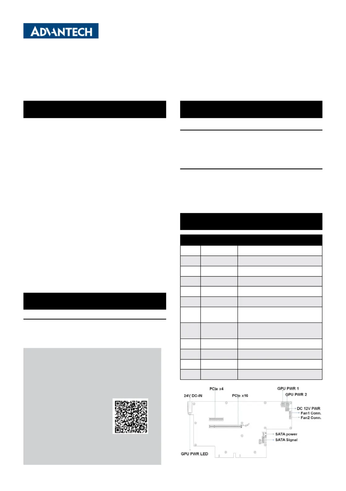
Connectors
No.ItemFunction
1DCIN124V
DC
in
2PPCIE1PCIe x16 slot
3PPCIE2PCIe p1-x4 slot
4SATAPWR14-pin SATA power connector (5V)
5SATA signal connectorSATA1
6GPUPWR1
6-pin power connector for GPU card
(12V, 17A)
7GPUPWR2
6-pin power connector for GPU card
(12V, 17A)
8DC12VOOUT14-pin power connector (12V, 5A)
9SYSFAN14-pin fan connector
10SYSFAN24-pin fan connector (reserved)
11LEDGPU card power status
Specications(Cont.) Packing List
For more information on this and other Advantech
products, please visit our website at:
http://www.advantech.com
http://www.advantech.com/eplatform
For technical support and service, please visit our
support website at:
This manual is for MIC-75G20-10 Rev. C1.
Part No. 20415G2012
Printed in China
3rd Edition
October 2024
I/O Connectors
Specications
Product specificaties
| Merk: | Advantech |
| Categorie: | Niet gecategoriseerd |
| Model: | MIC-75G20 |
Heb je hulp nodig?
Als je hulp nodig hebt met Advantech MIC-75G20 stel dan hieronder een vraag en andere gebruikers zullen je antwoorden
Handleiding Niet gecategoriseerd Advantech

5 Juni 2026
5 Juni 2026
3 Juni 2026
2 Juni 2026
1 Juni 2026
1 Juni 2026
1 Juni 2026
27 Mei 2026
1 Mei 2026
29 April 2026
Handleiding Niet gecategoriseerd
Nieuwste handleidingen voor Niet gecategoriseerd
8 Juni 2026
8 Juni 2026
8 Juni 2026
8 Juni 2026
8 Juni 2026
8 Juni 2026
8 Juni 2026
8 Juni 2026
8 Juni 2026
8 Juni 2026