Advantech ASMB-818 Handleiding
Advantech Moederbord ASMB-818
Bekijk gratis de handleiding van Advantech ASMB-818 (3 pagina’s), behorend tot de categorie Moederbord. Deze gids werd als nuttig beoordeeld door 61 mensen en kreeg gemiddeld 4.3 sterren uit 6 reviews. Heb je een vraag over Advantech ASMB-818 of wil je andere gebruikers van dit product iets vragen? Stel een vraag
Pagina 1/3
ASMB-818 Startup Manual 1
Before you begin installing your card, please make sure that
the following items have been shipped:
•1 x ASMB-818 Startup Manual
•1 x SATA data cables
•1 x SATA power cables
•2 x CPU power cables (8P)
•1 x CPU carrier - E2A (XCC)
•1 x CPU carrier - E2B (MCC)
•1 x PCIe I/O support
•1 x front panel converter cable
•1 x I/O port bracket
•1 x M.2 screw
If any of these items are missing or damaged, please con-
tact your distributor or sales representative immediately.
Standard M/B Functions
•CPU: LGA4710 6th Gen Intel® Xeon® Scalable proces-
sor
•BIOS:AMI 512 Mbit SPI BIOS
•System Memory: 8 x DDR5 6400 MT/s registered ECC
DIMM, Max. capacity 2TB
ASMB-818 Series LGA 4710 6th Gen Intel® Xeon®
Scalable ATX Server Board with 8 DDR5, 3 PCIe x16,
5 SATA3, 4 USB 3.2 (Gen1), 1 M.2, Dual 10GbE, IPMI
Startup Manual
Note: Due to the inherent limitations of older PC ar-
chitectures, the system may not fully detect 2TB
RAM when 2TB RAM is installed.
•SATA Interface: Asmedia ASM1165: 4 x SATA 3.0 (6
Gb/s) via Slim-SAS HD, 1 x SATA 3.0 (6Gb/s)
•Serial Ports: One at the rear I/O, only supporting RS-232
•Watchdog Timer: 255-level timer intervals
•USB Port: Supports up to 4 x USB 3.2 (Gen1) ports (2
rear ports, 2 ports from the onboard 20-pin header) and 5
x USB 2.0 ports (1 x Type-A, 4 rear ports)
VGA Interface
•Chipset: ASPEED AST2600
•Display Memory: 64 MB
•Resolution: Supports VGA, resolution up to 1920 x 1200
@ 60 Hz refresh
Ethernet Interface
•Interface: 10/100/1000/2500 Mbps & 10 GbE Base-T
•Controller: LAN1/2: Intel I226; LAN3/4: Intel X710
Mechanical and Environmental
•Dimensions (L x W): 244x304mm(9.6″x12″)
•Power Supply Voltage: +3.3 V, +5 V, +12 V, +5 Vsb
•Power Consumption (mainboard only, excluding I/O
device): Max. load: +3.3 V @ 0.59 A, +5 V@ 1.92 A,
+12 V @ 6.65 A,+5 Vsb @ 0.01 A, +12V_8P_1 @ 17.22
A, +12V_8P_2 @ 15.91 A
•Operating Temperature: 0 ~ 60°C (depending on CPU)
•Net Weight: 0.97 kg
Theboardhasanumberofjumpersthatallowyoutocongure
your system to suit your application. The table below lists the
function of each of the jumpers and connectors.
Connectors
LabelFunction
ATXPWR1
ATX 24-pin main power connector
ATX12V1, ATX12V2Processor power connector (for CPU0)
BH2For optional battery kit
BIOS_SKT1BIOS SPI ROM
COM1Serial port: RS-232
CPUFAN0CPU FAN connector
Specications
Packing List
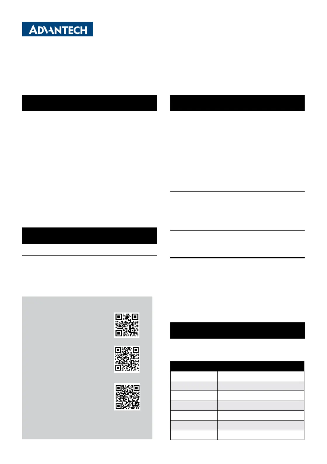
For more information on this and other Advantech
products, please visit our website at:
http://www.advantech.com
For technical support and service, please visit our
support website at:
http://support.advantech.com
Register your products on our website and get 2
months extra warranty for free at:
http://www.register.advantech.com
This manual is for the ASMB-818 Series Rev. A1.
Part No. 2042081800
Printed in China
1st Edition
May 2025
Specications(Cont.)
Jumpers and Connectors
Product specificaties
| Merk: | Advantech |
| Categorie: | Moederbord |
| Model: | ASMB-818 |
Heb je hulp nodig?
Als je hulp nodig hebt met Advantech ASMB-818 stel dan hieronder een vraag en andere gebruikers zullen je antwoorden
Handleiding Moederbord Advantech

11 December 2025
9 December 2025
2 December 2025
30 September 2025
30 September 2025
29 September 2025
29 September 2025
29 September 2025
29 September 2025
30 Juli 2025
Handleiding Moederbord
Nieuwste handleidingen voor Moederbord
14 Juli 2026
13 Juli 2026
13 Juli 2026
13 Juli 2026
13 Juli 2026
12 Juli 2026
24 Juni 2026
23 Juni 2026
22 Juni 2026
18 Juni 2026