Advantech ADAM-3955 Handleiding
Advantech Niet gecategoriseerd ADAM-3955
Bekijk gratis de handleiding van Advantech ADAM-3955 (6 pagina’s), behorend tot de categorie Niet gecategoriseerd. Deze gids werd als nuttig beoordeeld door 3 mensen en kreeg gemiddeld 4.7 sterren uit 7 reviews. Heb je een vraag over Advantech ADAM-3955 of wil je andere gebruikers van dit product iets vragen? Stel een vraag
Pagina 1/6
STARTUP MANUAL
ADAM-3955
50-pin SCSI DIN-rail Wiring Board
Declaration of Conformity
FCC Class A
This equipment has been tested and found to comply with
the limits for a Class A digital device, pursuant to part 15
of the FCC Rules. These limits are designed to provide
reasonable protection against harmful interference when
the equipment is operated in a commercial environment.
This equipment generates, uses, and can radiate radio
frequency energy and,if not installed and used in
accordance with the instruction manual, may cause
harmful interference to radio communications.
Operation of this equipment in a residential area is likely
to cause harmful interference in which case the user will
be required to correct the interference at his own expense.
CE
This product has passed the CE test for environmental
specications when shielded cables are used for external
wiring. We recommend the use of shielded cables. This
kind of cable is available from Advantech. Please contact
your local supplier for ordering information.
Notes
For more information on this and other Advantech
products, please visit our websites at:
http://www.advantech.com
http://www.advantech.com/eAutomation
For technical support and service:
http://support.advantech.com/
This startup manual is for the ADAM-3955
Part No: 20033955002nd Edition
Janauary 2014
Features
1. DIN-rail wiring board for PCI-1220U/1240U/ PCI-
1245/1245E/1245L/1265 application.
2. Dimensions (W x L x H): 103 x 120 x 45mm
(4.12” x 4.8” x 1.8”)
3. DB-26 connector
4. LED indicators
Overview
The ADAM-3955 terminal board provides convenient and
reliable signal wiring for PCI-1220U/1240U/1245/1245E
/1245L/1265 with 50-pin SCSI-II connector. Its D-SUB
26P type connectors give you the quick and easy way to
connect to the Panasonic A5/MINAS A , Yaskawa Sigma
5 , Mitsubishi J3S and Delta A2 servo motors.
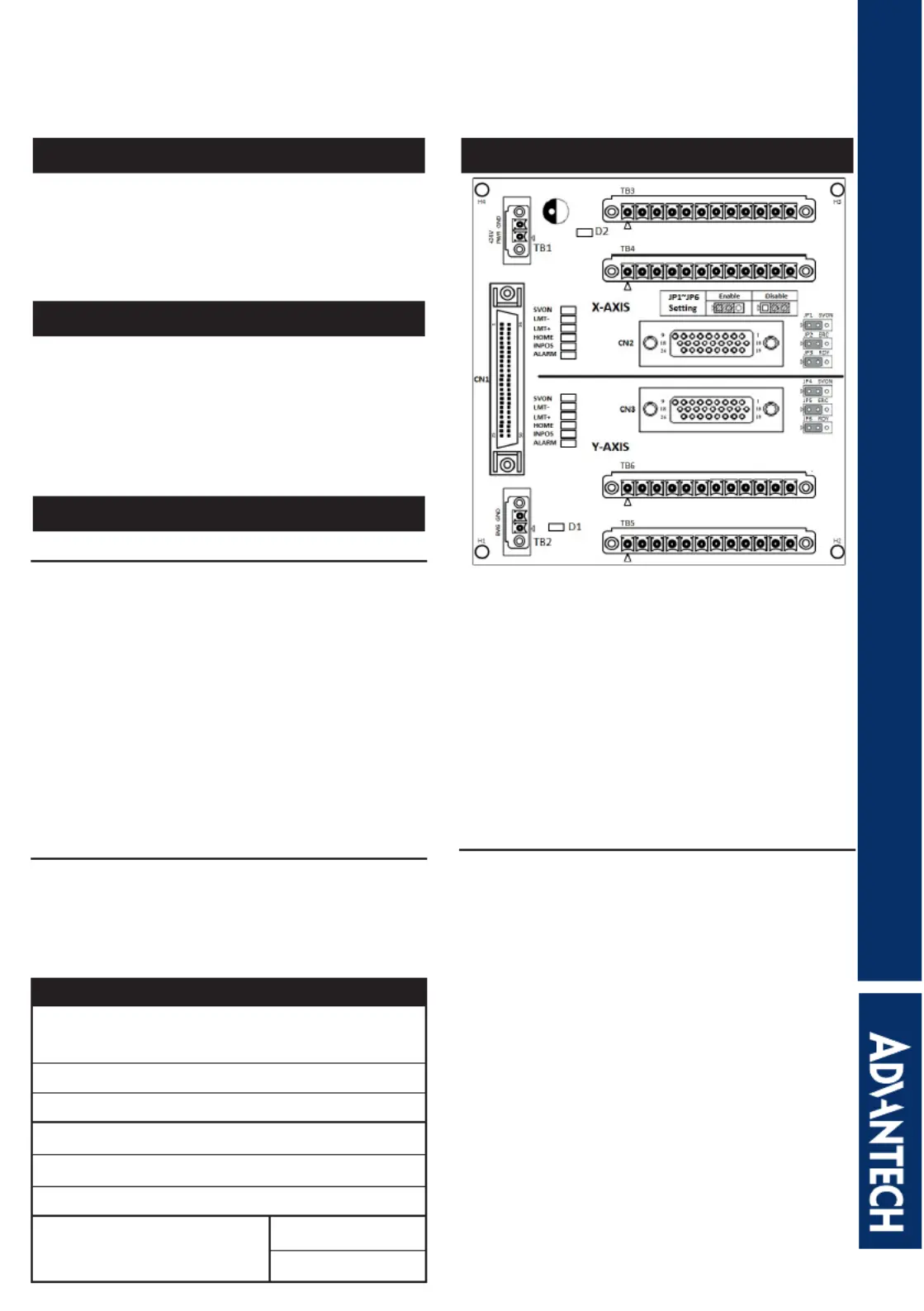
Board Components
Optional Cables
PCL-10251-1E 100-pin SCSI to Two 50-pin SCSI
Cable, 1m
PCL-10251-3E 100-pin SCSI to Two 50-pin SCSI
Cable, 1m
PCL-10152-1E 50-pin SCSI Cable, 1m
PCL-10152-3E 50-pin SCSI Cable, 3m
PCL-10153PA5-2E DB26 to SCSI-50 Cable for
Panasonic A5, 2m
PCL-10153PA5LS-2E DB26 to SCSI-50 Cable for
Panasonic MINAS A, 2m
PCL-10153YS5-2E DB26 to SCSI-50 Cable for
Yatsukawa Sigma 5, 2m
PCL-10153MJ3-2E DB26 to SCSI-50 Cable for
Mitsubishi J3S, 2m
PCL-10153DA2-2E DB26 to SCSI-50 Cable for Delta
A2, 2m
Note:
1. PIN 1 on TB3(TB5) is “power source” and PIN 1 on
TB4(TB6) is “pulse output”.
If connecting “power source” to “pulse output” , the
current will damage the line driver & related components
on the motion card connected to ADAM-3955.
2. Using which is included in package to protection key
avoid the accident to damage the motion board.
The assembly method is described in the end of this
manual.
Product specificaties
| Merk: | Advantech |
| Categorie: | Niet gecategoriseerd |
| Model: | ADAM-3955 |
Heb je hulp nodig?
Als je hulp nodig hebt met Advantech ADAM-3955 stel dan hieronder een vraag en andere gebruikers zullen je antwoorden
Handleiding Niet gecategoriseerd Advantech

5 Juni 2026
5 Juni 2026
3 Juni 2026
2 Juni 2026
1 Juni 2026
1 Juni 2026
1 Juni 2026
27 Mei 2026
1 Mei 2026
29 April 2026
Handleiding Niet gecategoriseerd
Nieuwste handleidingen voor Niet gecategoriseerd
8 Juni 2026
8 Juni 2026
8 Juni 2026
8 Juni 2026
8 Juni 2026
8 Juni 2026
8 Juni 2026
8 Juni 2026
8 Juni 2026
8 Juni 2026