Wolf WX60-10B Handleiding
Bekijk gratis de handleiding van Wolf WX60-10B (27 pagina’s), behorend tot de categorie Fornuis. Deze gids werd als nuttig beoordeeld door 96 mensen en kreeg gemiddeld 4.7 sterren uit 3 reviews. Heb je een vraag over Wolf WX60-10B of wil je andere gebruikers van dit product iets vragen? Stel een vraag
Pagina 1/27
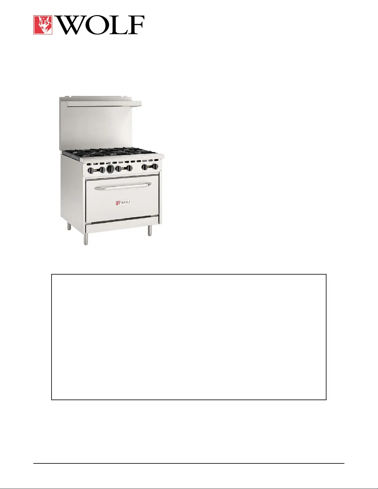
WX RANGE
WX24
WX36
WX60
WX60F
-NOTICE -
This Manual is prepared for the use of trained Hobart Service Technicians and should not
be used by those not properly qualified.
This manual is not intended to be all encompassing. If you have not attended a Hobart Service
School for this product, you should read, in its entirety, the repair procedure you wish to
perform to determine if you have the necessary tools, instruments and skills required to
perform the procedure. Procedures for which you do not have the necessary tools,
instruments and skills should be performed by a trained Hobart Service Technician.
The reproduction, transfer, sale or other use of this manual, without the express written
consent of Hobart, is prohibited.
This manual has been provided to you by ITW Food Equipment Group LLC ("ITW FEG")
without charge and remains the property of ITW FEG, and by accepting this manual you agree
that you will return it to ITW FEG promptly upon its request for such return at any time in the
future.
SERVICE MANUAL
F45992 (1123)
WOLFIS A DIVISION OF ITW FOOD EQUIPMENT GROUP, LLC 3600 NORTH POINT BLVD., BALTIMORE, MD 21222
Product specificaties
| Merk: | Wolf |
| Categorie: | Fornuis |
| Model: | WX60-10B |
Heb je hulp nodig?
Als je hulp nodig hebt met Wolf WX60-10B stel dan hieronder een vraag en andere gebruikers zullen je antwoorden
Handleiding Fornuis Wolf

14 Mei 2026
20 April 2026
22 Januari 2026
21 Januari 2026
21 Januari 2026
19 Januari 2026
19 Januari 2026
16 December 2025
21 November 2025
21 November 2025
Handleiding Fornuis
Nieuwste handleidingen voor Fornuis
19 Mei 2026
19 Mei 2026
19 Mei 2026
19 Mei 2026
19 Mei 2026
19 Mei 2026
19 Mei 2026
19 Mei 2026
18 Mei 2026
18 Mei 2026