Whirlpool WMH54521JV Handleiding
Bekijk gratis de handleiding van Whirlpool WMH54521JV (12 pagina’s), behorend tot de categorie Magnetron. Deze gids werd als nuttig beoordeeld door 36 mensen en kreeg gemiddeld 4.7 sterren uit 18.5 reviews. Heb je een vraag over Whirlpool WMH54521JV of wil je andere gebruikers van dit product iets vragen? Stel een vraag
Pagina 1/12

Th ris p oduct is uitable for s u nse above electric or gas cooki g products up to d i an ncluding 36" (91 4 . cm w ) ide. See the “I tallations n
Requirements otes” r n section fo further .
Th s in f rese in tallation structions cover di fe ent models. The appea ce of r paran you rticular model may f di fer lig tl s h y from he tr n t illus atio
i n s.n these installatio instruction
Yo can b k ed seriousl nju d u u e ill or y i re if yo do mmen't i diately
You can be killed or seriously injured if you don't follow
Your safety and the safety of others are very important.
follow instructions.
instructions.
DANGER
WARNING
MI WACRO VE HOOD COMBINATI SAFON ETY ...... ... ... ..... ... .. .... . .1
INSTALLATION RE IREMEQU NTS .... . ... ... . ... .. .. ... .. ................ ...... ...2
Tool d s n a Parts .... . ... ... . . ... ... ... ... ..... .. .. ... .. ... ... .... ... ... .... ...... ............2
Remove Cardboard Template .... ... .. ..... ... .... .. .... ............. ...... ... ..2...
Location Requirements .... . ... ... .. .. .. .. .. ... . . .......... .. .... . ... ... ...... .... .....2
Product Dimensio ns ...... ... ..... .. ... . ... .. .... . ... . .... .. ... ...... ... ... ... .3.... ... ...
Electrical Requi rements .... . ... ... . . ... ... ... ... ..... .. .. ... .. ... ... .... ... ... ........3
INSTALLATION I NS .... . .NSTRUCTIO .. .. .. ... .. .. .. ... . . .......... .. .... . ... ..4...
Remove Mounting lat P e .... . ... . ... .. .. .. .. .. .. .... . . ... .... .. .... ............. ...... .4
Rotate Blo wer Motor .... ... .. ..... ... .. ... . ... .... ...... .. .... . ... ... ... ...... .... ... ...4
Locate Wall Stud(s ) .... ... .. ..... ... .... .. .... ... ...... .......... ...... ... ... .....6.... ...
Mark Rear Wall .... ... .. ..... ... .... .. .... ...... ....... ...... ...... ... ... ... .....7.... ... ....
Drill Hole ins Rear Wall .... ... ....... ...... ... .... ... ...... .......... ...... ... ... .7.... ..
Attach Mou ti n ng Plate to Wall .... . ... . ... .. .. .. .. .. .. .... . . ... .... .. .... ..........8
Prepare Upper Cabinet .... . ... . ... .. .. .. .. .. .. .... . . ... .... .. .... ............. ...... ..8
In ssemblstall Damper A y .... ... ....... ...... ... .... ... ...... .......... ...... ... ..9....
Ins rtall the Mic owave Oven .... ... .. ..... ... .. ... . ... .... ...... .. .... . ... ... ..9... ....
Complete Installation ...... ... ... . . ... .. .. .. .. .... . ... . . ...... .. ... ... ....... ... ...10...
VE NNTI G DESIGN SPECIFICATI S ....ON .. ... ........... .. .... . ... ... .11... ....
ASSISTANCE ..... ..... ... . ... .. ... ...... ... .... ... ...... .......... .... ....... .. ... .12.... .....
Replacement Parts .... . ... . ... .. .. .. .. .. .. .... . . ... .... .. .... ............. ...... ... .12...
Accessories ..... ..... ......... ...... ... ... ... . . ....... ... ... .. ... .... .... .... ...... .. ... ...12
W11199602B

2
Tools Needed
Gather the required and parts fore artin n on. tools be st g i stallati
R and ead follow the instru ns prov with any ols ctio ided to
lis d here.te
Measuring tape
Pencil
Masking e ortap
thum cksbta
Scissors
No. 2 Phillips screwdriver
No. 3 Phillips screwdriver
for ¹⁄₄ - 20 x 3" (7.62 cm)
bolts
Drill
³⁄₁₆" (5 mm), ³⁄₈" (10 mm),
⁵⁄₈" (16 mm) drill bits
³⁄₄" (19 mm) hole saw
D onal wire tin ersiag cut g pli
Stud nderfi
⁷⁄₁₆" (11.11 mm) ketsoc
wrench (or box wrench for)
¹⁄₄" x 2" (6.35 mm x
5.08 ) g screws cm la
1½" (3.8 cm) am. holedi
dr l w d or metalil bit for oo
cabinet
Keyh e sawol
Caulking gun and
weatherpr caulkingoof
compound
Duct tape
Parts Supplied
For in rm on on reorfo ati deri ee ng, s th R ment ts” e “ eplace Par
s on.ecti
NOTE: The hardware ite listems d here are for w studs. ood
For her types of w structures, sure to u approt all be se opriate
fasteners.
A B C D E F G
H
A. ³⁄₁₆
-24 x 3" round-head
bolts (2)
F.
G.
H.
B. ¹⁄₄-20 x 3" flat-head
bolts (2)
C. Washers (2)
D. ³⁄₁₆" toggle nuts (2)
E. ¹⁄₄" x 2"
)1( gnihsub droc ylppus rewoP
ro llaw rof( ylbmessa repmaD
roof venting)
Not Shown:
Upper cabinet platetem
Mounting pla ached tote (att
ba of micr ave oven)ck ow
Cardboard plate (part oftem
packaging) or wall platetem
Al greuminum ase tersfil
Char al ers pending onco filt (De
model, charcoal ters mayfil
not cluded. See Userbe in
Instru ns.)ctio
NOTE: Depending on m l, aluminum grode ease filter and charcoal
filter may be combined.
Materials Needed
Standard tings for wfit all or roof tin ven g. See the “Venting
Design S ” s ion.pecifications ect
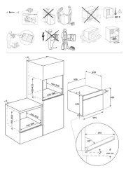
Ch k th pening where the microw oven w be ins ed. ec e o ave ill tall
Th locate ion must provide:
Minimum ins ion dimensions. S the “ s iontallat ee In tallat
Dimensions” lus on. il trati
Minimum one 2" x 4" (50.8 x 101.6 mm) w stu andood wall d
minimum " (10 mm³⁄₈ ) icth kness dryw aster/ th withinall or pl la
cabin pening.et o
Su r weight of 150 lbs (68pport fo kg) which includes
microwav oven an tems ed ins he microwavee d i plac ide t
oven and u er binet.pp ca
Groun d ou ins u r binet. S thede electrical tlet ide ppe ca ee
“E r l Requirements” s ion.lect ica ect
NOTES:
If ins talling the microwave oven near a t sidewall, makelef
su re there is at least 6" (15.2 cm clearan tween the) of ce be
wall and the microwave oven so th the door can open fully.at
emo S models have a pocket handle. If ins lling the microwaveta
nea r a right side wall, make sure there is at least 3 inches of
clearance between wall and microwave oven so you can
grab the handle integrated inside the door.
S om binet and e ca building materials are n designed toot
withstand the heat produced by the microwave oven for
cookin Check with your builder or inet su lier to makeg. cab pp
sure that the materials used will not discolor , laminate, orde
sustain other damages.
Special Requir ntseme
For Wall Ven Insting tallation Only:
Cutout mus fr any obs u ions so the vent tst be ee of tr ct that fi
pr rly anope d the damper pens freely and fully.blade o
For Roof Venting I allatio Only:nst n
If you are using a r tangularec -to-roun ans ion d tr it piece,
the 3" (7.6 cm) clearance n ds is ove the microwaveee to ex t ab
oven so th the damper canat blade open freely and fully.
Se ece “R tangu r to Round Trans ion” lustr on in thela it il ati
“Ven ng Design ions” sti Specificat ection.
The cardboard e from the f the microwave oven piec top o
packaging is per . The e ins the perforation forated piec ide
is or use as a rear wall tem ate. f pl
Depending on your m l, t may use fu arton for ode i ll c box
packin then s remove r r em e steps, butg, kip ca dboa d t plat
use the wall tem r " rk Rear Wall" t of ins on.plate fo Ma par tallati
1. Cu along the rfor ion to separate the tem e from thet pe at plat
rest of the cardboard ging.packa
2. Set the cardboard tem o the s e and referplate t id to it during
the “Mark Rear Wall” part of ins tion.talla
lag screws (2)
#6 x ³ ₈/ " Sheet metal screws (2)

3
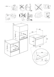
Installation Dimensions
NOTE: The grounded 3 prong outlet must be inside the upper
cabinet. See the “Electrical Requirements” section.
12" (30.5 cm) min.
14" (35.6 cm) max.
30"
(76.2 cm)
min.
A B
upper cabinet and
side cabinet depth
30"
(76.2 cm)
typical*
66" (167.6 cm) min.
A. 2" x 4" (5.08 x 10.16) wall stud
B. Grounded 3 prong outlet
*30” (76.2 cm) is typical for 66” (167.6 cm) installation height.
Exact di sio s men n m /ay vary depending on type of range
cooktop below.
NOTE: To ensur e good performance, do not obstruct top vent
airflow. If cabinets are deeper than 14” (35.6 cm) but no mor e
than 15” (38.1cm), use the bump out mounting kit r ee pplacing the
I bar mounting plate fr om the wall. The bump out mounting kit
(part # W11185746) is not provided but can be purchased
from Whirlpool.
Product Dimensions
16 "¹⁄₄
(41.3 cm)
*Overall depth of product will vary slightly depending on
door design.
Electrical Requirements
Electrical Shock Hazard
Plug into a grounded 3 prong outlet.
Do not remove ground prong.
Do not use an adapter.
Do not use an extension cord.
Failure to follow these instructions can result in death,
fire, or electrical shock.
WARNING
Observe all governing codes and ordinances.
Required:
A Hz, AC o120 V, 60 nly, or elect15 20 Arical suppl y
wi h us rcui re rt a f e or ci t b ake
Recommended:
■A time-delay fuse or time-delay circuit breaker
■A separate circuit serving only this microwave oven
GROUNDING INSTRUCTIONS
SAVE THESE INSTRUCTIONS
■For all cord connected appliances:
The microwave oven must be grounded. In the event of
an electrical short circuit, grounding reduces the risk of
electric shock by providing an escape wire for the electric
current. The microwave oven is equipped with a cord
having a grounding wire with a grounding plug. The plug
must be plugged into an outlet that is properly installed
and grounded.
WARNING: Improper use of the grounding plug can
result in a risk of electric shock. Consult a qualified
electrician or serviceman if the grounding instructions are
not completely understood, or if doubt exists as to whether
the microwave oven is properly grounded.
Do not use an extension cord. If the power supply cord is
too short, have a qualified electrician or serviceman install
an outlet near the microwave oven.
17¹⁄₈"
(43.5 cm)
+/- ³⁄₁₆"
(0.5 cm)
16³⁄
Up to
₄"
(42.5 cm)*
cm)
29⁷⁄₈" (76.0
I bar mounting plate Bump out mounting bracket
14"
12" DEEPER 15"14" DEEPER
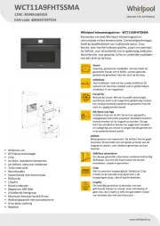
Product specificaties
| Merk: | Whirlpool |
| Categorie: | Magnetron |
| Model: | WMH54521JV |
Heb je hulp nodig?
Als je hulp nodig hebt met Whirlpool WMH54521JV stel dan hieronder een vraag en andere gebruikers zullen je antwoorden
Handleiding Magnetron Whirlpool
14 Juli 2025
14 Juli 2025
5 Juli 2025
4 Juli 2025
4 Juli 2025
4 Juli 2025

4 Juli 2025

4 Juli 2025
1 Juli 2025
14 Mei 2025
Handleiding Magnetron
- Domoclip
- Frigidaire
- Microstar
- Omega
- Champion
- Mepamsa
- Commercial Chef
- Tower
- Holland Electro
- Adelberg
- Mei
- Jenn-Air
- Cata
- Ilve
- Delonghi
Nieuwste handleidingen voor Magnetron
30 Juli 2025
29 Juli 2025

29 Juli 2025

28 Juli 2025
28 Juli 2025
28 Juli 2025
28 Juli 2025
28 Juli 2025

28 Juli 2025
28 Juli 2025