Whirlpool WMH54521HV Handleiding
Bekijk gratis de handleiding van Whirlpool WMH54521HV (16 pagina’s), behorend tot de categorie Magnetron. Deze gids werd als nuttig beoordeeld door 46 mensen en kreeg gemiddeld 5.0 sterren uit 23.5 reviews. Heb je een vraag over Whirlpool WMH54521HV of wil je andere gebruikers van dit product iets vragen? Stel een vraag
Pagina 1/16

MICROWAVE HOOD COMBINATION
INSTALLATION INSTRUCTIONS
This product is suitable for use above electric or gas cooking products up to and including 36" (91.4 cm) wide. See the “Installation
Requirements” section for further notes.
These installation instructions cover different models. The appearance of your particular model may differ slightly from the illustration
in these installation instructions.
Table of Contents
MICROWAVE HOOD COMBINATION SAFETY
W11401886A
MICROWAVE HOOD COMBINATION SAFETY ............................1
INSTALLATION REQUIREMENTS ................................................. 2
Tools and Parts .............................................................................2
Remove Cardboard Template ......................................................2
Location Requirements ................................................................2
Electrical Requirements ...............................................................3
INSTALLATION INSTRUCTIONS ................................................... 4
Remove Mounting Plate ............................................................... 4
Rotate Blower Motor ....................................................................4
Locate Wall Stud(s) ......................................................................7
Mark Rear Wall .............................................................................7
Drill Holes in Rear Wall .................................................................8
Attach Mounting Plate to Wall .....................................................8
Prepare Upper Cabinet ................................................................9
Install Damper Assembly ...........................................................10
Install the Microwave Oven ........................................................10
Complete Installation .................................................................11
VENTING DESIGN SPECIFICATIONS ........................................12
ASSISTANCE 14 ................................................................................
Replacement Parts .....................................................................14
Accessories 14 ................................................................................

2
INSTALLATION REQUIREMENTS
Tools and Parts
Tools Needed
Gather the required tools and parts before starting installation.
Read and follow the instructions provided with any tools listed
here.
■Measuring tape
■Pencil
■Masking tape or
thumbtacks
■Scissors
■No. 2 Phillips screwdriver
■No. 3 Phillips screwdriver
for 1/4 - 20 x 3" (7.6 cm)
bolts
■Drill
■3/16" (5 mm), 3/8" (1 cm),
5/8" (1.6 cm) drill bits
■3/4" (1.9 cm) hole saw
■Diagonal wire cutting pliers
■Stud nder
■7⁄16" (1.1 cm) socket
wrench (or box wrench) for
1/4" x 2" (6.4 mm x 5.1cm)
lag screws
■11/2" (3.8 cm) diam. hole
drill bit for wood or metal
cabinet
■Keyhole saw
■Caulking gun and
weatherproof caulking
compound
■Duct tape
Parts Needed
For information on reordering, see the “Replacement Parts”
section.
NOTE: The hardware items listed here are for wood studs.
For other types of wall structures, be sure to use appropriate
fasteners.
NOTE: Depending on model, aluminum grease lter and
charcoal lter may be combined.
Materials Needed
■Standard ttings for wall or roof venting. See the “Venting
Design Specications” section.
Remove Cardboard Template
The cardboard piece from the top of the microwave oven
packaging is perforated. The piece inside the perforation is for
use as a rear wall template.
1. Cut along the perforation to separate the template from the
rest of the cardboard packaging.
2. Set the cardboard template to the side and refer to it during
the “Mark Rear Wall” part of installation.
Depending on your model, it may use full carton box for packing,
then skip remove cardboard template steps, but use the wall
template for "Mark Rear Wall" part of installation.
Location Requirements
Check the opening where the microwave oven will be installed.
The location must provide:
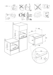
■Minimum installation dimensions. See the “Installation
Dimensions” illustration.
■Minimum one 2" x 4" (5.1 x 10.2 cm) wood wall stud and
minimum 3/8" (1 cm) thickness drywall or plaster/lath within
cabinet opening.
■Support for weight of 150 lbs (68 kg) which includes
microwave oven and items placed inside the microwave
oven and upper cabinet.
■Grounded electrical outlet inside upper cabinet. See the
“Electrical Requirements” section.
NOTES:
■If installing the microwave oven near a left sidewall, make
sure there is at least 6" (15.2 cm) of clearance between the
wall and the microwave oven so that the door can open fully.
■Some models have a pocket handle. If installing the
microwave near a right side wall, make sure there is at least
3 inches of clearance between wall and microwave oven so
you can grab the handle integrated inside the door.
■Some cabinet and building materials are not designed to
withstand the heat produced by the microwave oven for
cooking. Check with your builder or cabinet supplier to make
sure that the materials used will not discolor, delaminate, or
sustain other damages.
Special Requirements
For Wall Venting Installation Only:
■Cutout must be free of any obstructions so that the vent t
properly and the damper blade opens freely and fully.
For Roof Venting Installation Only:
■If you are using a rectangular-to-round transition piece, the
3" (7.6 cm) clearance needs to exist above the microwave
oven so that the damper blade can open freely and fully.
See “Rectangular to Round Transition” illustration in the
“Venting Design Specications” section.
A B C D E F G
H
A. 3/16 - 24 x 3" round-head
bolts (2)
B. 1/4 - 20 x 3" at-head bolts (2)
C. Washers (2)
D. 3/16" toggle nuts (2)
E. 1/4" x 2" lag screws (2)
F. #6 x 3/8" Sheet metal screws (2)
G. Power supply cord bushing (1)
H. Damper assembly (for wall or
roof venting)
Not Shown:
■Upper cabinet template
■Mounting plate (attached to
back of microwave oven)
■Cardboard template (part of
packaging) or wall template
■Aluminum grease lters
■Charcoal lters (Depending
on model, charcoal lters may
not be included. See User
Instructions.)

3
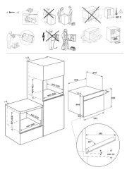
Installation Dimensions
NOTE: The grounded 3 prong outlet must be inside the upper
cabinet. See the “Electrical Requirements” section.
*30" (76.2 cm) is typical for 66" (167.6 cm) installation height.
Exact dimensions may vary depending on type of range/cooktop
below.
NOTE: To ensure good performance, do not obstruct top vent
airow. If cabinets are deeper than 14" (35.6 cm) but no more
than 15" (38.1 cm), use the bump out mounting kit replacing the
I bar mounting plate fr om the wall. The bump out mounting kit
(part # W11185746) is not provided but can be purchased from
Whirlpool.
*Overall depth of product will vary slightly depending on door
design.
Electrical Requirements
Observe all governing codes and ordinances.
Required:
■A 120 V, 60 Hz, AC only, 15 or 20 A electrical supply with a
fuse or circuit breaker
Recommended:
■A time-delay fuse or time-delay circuit breaker
■A separate circuit serving only this microwave oven
A. 2" x 4" (5.1 x 10.2 cm) wall stud
B. Grounded 3 prong outlet
12" (30.5 cm) min.
14" (35.6 cm) max.
30"
(76.2 cm)
min.
A B
upper cabinet and
side cabinet depth
30"
(76.2 cm)
typical*
66" (167.6 cm) min.
Product Dimensions
16¹⁄₄"
(41.3 cm)
17¹⁄₈"
(43.5 cm)
+/- ³⁄₁₆"
(0.5 cm)
17"
Up to
(43.2 cm)
*
cm)
29⁷⁄₈" (76.0
I bar mounting plate Bump out mounting bracket
12" DEEPER 14" 14" DEEPER 15"
GROUNDING INSTRUCTIONS
SAVE THESE INSTRUCTIONS
For all cord connected appliances:
The microwave oven must be grounded. In the event of
an electrical short circuit, grounding reduces the risk of
electric shock by providing an escape wire for the electric
current. The microwave oven is equipped with a cord
having a grounding wire with a grounding plug. The plug
must be plugged into an outlet that is properly installed
and grounded.
WARNING: Improper use of the grounding plug can
result in a risk of electric shock. Consult a qualified
electrician or serviceman if the grounding instructions are
not completely understood, or if doubt exists as to whether
the microwave oven is properly grounded.
Do not use an extension cord. If the power supply cord is
too short, have a qualified electrician or serviceman install
an outlet near the microwave oven.
Electrical Shock Hazard
Plug into a grounded 3 prong outlet.
Do not remove ground prong.
Do not use an adapter.
Do not use an extension cord.
Failure to follow these instructions can result in death,
fire, or electrical shock.
WARNING
Product specificaties
| Merk: | Whirlpool |
| Categorie: | Magnetron |
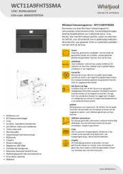
| Model: | WMH54521HV |
Heb je hulp nodig?
Als je hulp nodig hebt met Whirlpool WMH54521HV stel dan hieronder een vraag en andere gebruikers zullen je antwoorden
Handleiding Magnetron Whirlpool
14 Juli 2025
14 Juli 2025
5 Juli 2025
4 Juli 2025
4 Juli 2025
4 Juli 2025

4 Juli 2025

4 Juli 2025
1 Juli 2025
14 Mei 2025
Handleiding Magnetron
- Russell Hobbs
- Sheffield
- OBH Nordica
- Creda
- Kitchenware
- Balay
- Koenig
- Akai
- Goodmans
- Jocel
- Cecotec
- Ambiano
- Sage
- Boretti
- Beem
Nieuwste handleidingen voor Magnetron
30 Juli 2025
29 Juli 2025

29 Juli 2025

28 Juli 2025
28 Juli 2025
28 Juli 2025
28 Juli 2025
28 Juli 2025

28 Juli 2025
28 Juli 2025