Westinghouse WFE9756DD Handleiding
Westinghouse Oven WFE9756DD
Bekijk gratis de handleiding van Westinghouse WFE9756DD (52 pagina’s), behorend tot de categorie Oven. Deze gids werd als nuttig beoordeeld door 64 mensen en kreeg gemiddeld 4.6 sterren uit 6 reviews. Heb je een vraag over Westinghouse WFE9756DD of wil je andere gebruikers van dit product iets vragen? Stel een vraag
Pagina 1/52
1
USER MANUAL
90cm
COOKING
APPLIANCES
WFE9756DD
Enjoy peace of mind.
Register your appliance today.
Stay updated on better living services, safety notices and
shop for accessories.
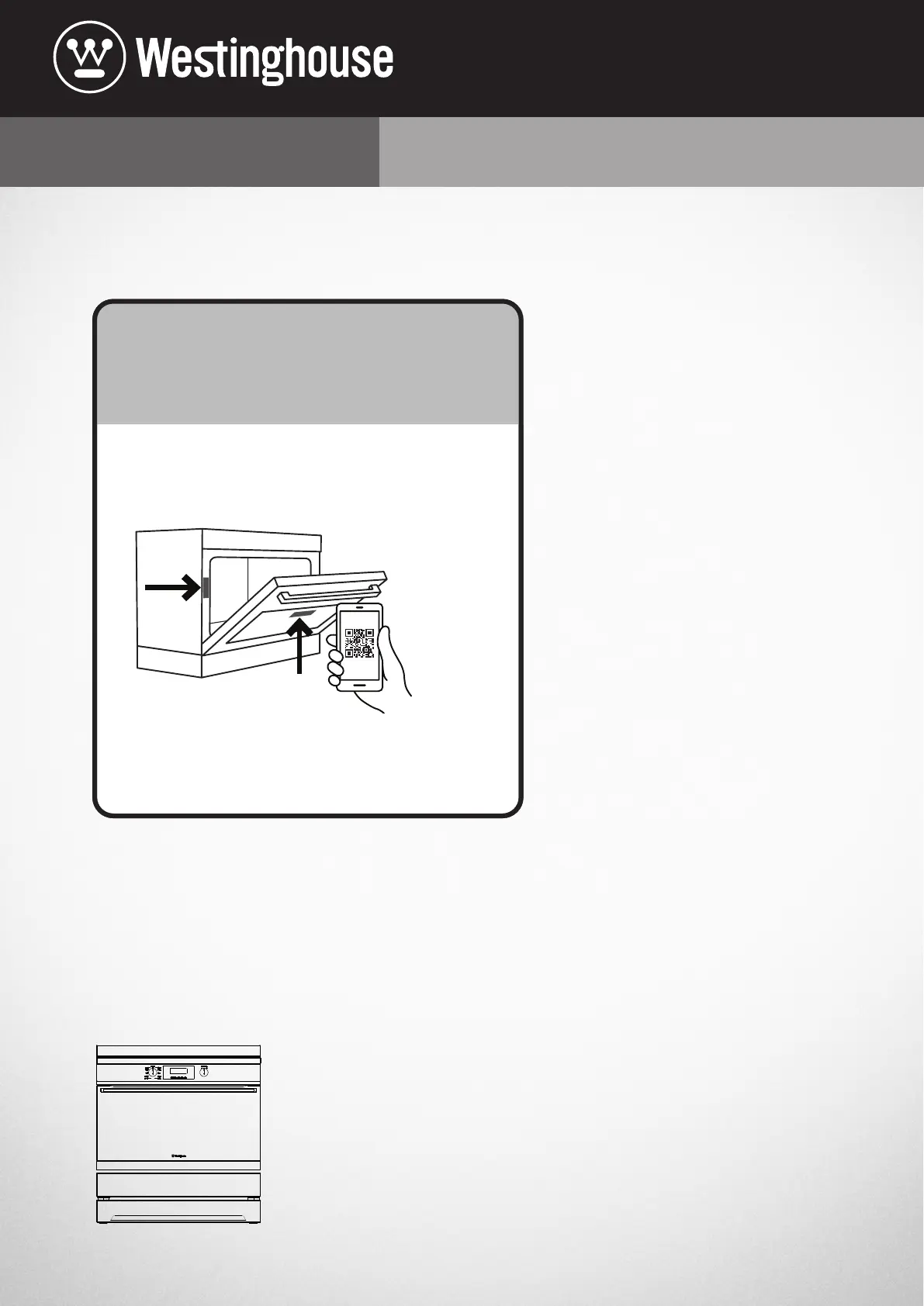
1.
Open the camera app on
your smartphone and
point at the QR code to scan
Product Regist
ration QR code is locat
ed on the
fr
ont of your appliance or inside the door rim*.
2.Tap the notification or link to open the registration form
3.Complete your details and enjoy peace of mind
*Exact location of QR code may vary depending on oven model
xy
z
M0120636 001 frame (FRAME FRONT ASSY)
M0146672 002 oven (OVEN CAVITY)
M0521130 001 chassis (CHASSIS VULCAN FS)
M0600012 001 WFEP9757DD
M0423712 002 panel (BACK PANEL)
0038009671_MM 002 panel (STORAGE BOTTOM PANEL)
0701009033_MM A screw (BACK PANEL SCREW.1)
0701009033_MM A screw (BACK PANEL SCREW.2)
0701009033_MM A screw (BACK PANEL SCREW.3)
0701009033_MM A screw (BACK PANEL SCREW.4)
0701009033_MM A screw (BACK PANEL SCREW.5)
0701009033_MM A screw (BACK PANEL SCREW.6)
0701009033_MM A screw (BACK PANEL SCREW.7)
0701009033_MM A screw (BACK PANEL SCREW.8)
0701009033_MM A screw (BACK PANEL SCREW.9)
0701009033_MM A screw (LOWER BRACE SCREW.1)
0701009033_MM A screw (LOWER BRACE SCREW.2)
0701009033_MM A screw (LOWER BRACE SCREW.3)
Product specificaties
| Merk: | Westinghouse |
| Categorie: | Oven |
| Model: | WFE9756DD |
Heb je hulp nodig?
Als je hulp nodig hebt met Westinghouse WFE9756DD stel dan hieronder een vraag en andere gebruikers zullen je antwoorden
Handleiding Oven Westinghouse

7 Mei 2026
28 Juli 2025
8 December 2024
15 November 2024
24 September 2024
22 Augustus 2024
22 Augustus 2024
22 Augustus 2024
22 Augustus 2024
21 Augustus 2024
Handleiding Oven
Nieuwste handleidingen voor Oven
24 Juli 2026
24 Juli 2026
23 Juli 2026
23 Juli 2026
22 Juli 2026
21 Juli 2026
20 Juli 2026
20 Juli 2026
16 Juli 2026
14 Juli 2026