Uni-T UT136D Handleiding
Uni-T
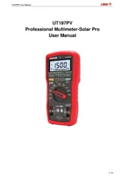
Multimeter
UT136D
Bekijk gratis de handleiding van Uni-T UT136D (2 pagina’s), behorend tot de categorie Multimeter. Deze gids werd als nuttig beoordeeld door 45 mensen en kreeg gemiddeld 4.4 sterren uit 23 reviews. Heb je een vraag over Uni-T UT136D of wil je andere gebruikers van dit product iets vragen? Stel een vraag
Pagina 1/2

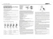
Measurement Operation
First check on 9V battery, then turn rotary switch to
the measuring position. If the low battery, “ ” sign.
will be displayed on LCD panel. Nearly to “ ” sign
on the meter front panel terminal input which alarm
not exceed the testing voltage and current input value
limitation.
A. DC/ AC Voltage Measurement (See figure 1)
figur 1e
1. In each range, the meter has an input impedance
of This loading effect can cause measurement 10MΩ.
err or s in high impedance circuits. If the circuit
impedance is less than or equal to the error is 10kΩ,
negligible (0.1% or less).
2. Press SELECT to switch AC or DC voltage
measurement.
3. The display value of AC measurement is effective
value of sine wave( average value).
4. The mV AC range can obtain only under 400
manual mode.
Note:
To avoid possibly damages to the meter, please do
not attempt to input higher than 500V.
To avoid electrical shock, please pay attention during
the high voltage measurement.
B. Capacitor Measurement (UT136B only, figure 2).
figure 2
1 M. The eter will display a xed value as below which fi
is the eter internal fixed distributed capacitance M
value. To ensure accuracy when measuring a small
value of capacitance, the tested value must subtract
this value, REL mode can help on that.
2. It is normal to take several seconds to obtain a
stable reading when testing a high value capacitor.
3. To avoid possibly damages to the meter, please do
not attempt to input higher than DC and 33V rms 60V
AC.
7. attery in meter: 9V F22 or NEDA 4 or B 6 160
IEC6LR61
8. Deficiency of Built in Battery: LCD display “ ”.
9. Product size: 72mm×137mm×35mm
10. Net Weight: About 200g (battery include)
11. Conform: CE
Button function and auto power off
1. HOLD button
Press HOLD to enter and exit hold mode in any mode
except frequency measurement.
2. buttonSELECT
Press bu tton to select th e alternate SEL ECT
functions including AC/DC voltage, AC/DC current,
auto and manual ranging, frequency and duty cycle.
Used as REL function button under resistance
measurement.
3. AUTO POWER OFF
To preserve battery life, the automatically goes Meter
into a “sleep” mode if you do not press any button for
around 5 minutes. The eter can be activated by 1 M
pressing any button, then returns to the display for
the function selected previously. To disable the sleep
mode function, press SELECT button while turning on
the meter.
4. BUZZER
The buzzer phonate go with every time button be
effectual pressed. When the meter will auto power off
in minutes the buzzer beeps 5 times. power 1 Before
off there will be a long time buzzer beeps.
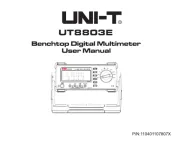
UT136A/B/C/D Operating Manual
UT136A/B/C/D
Handheld Digital Multimeter
Operating Manual
Safety Information
M 136A/Beter UT /C/D complies with the standard
IEC/EN , in pollution degree 2, overvoltage 61010-1
category (CAT II V and double insulation. Use 600 )
the meter only as in this operating manual, specified
otherwise the protection provided by the meter may
be impaired.
1 B. efore using the meter inspect the case. Do not
use the meter if it is damaged or the case (or part
of the is removed. Look for cracks or missing case)
plastic. Pay attention to the insulation around the
connections.
2. Inspect the test leads for damaged insulation or
exposed metal. Replace damaged test leads with
identical model number or electrical specifications
before using the meter.
3. Replace the battery as soon as the battery
indicator “ ” Appears. With a low battery, the
meter might produce false readings that can lead to
electric shock and personal injury.
4. When measurement is on / off against the correct
testing position.
5. Do not apply more that the rated voltage, as
marked on the meter in order to avoid possible
electric shock or personal injury and avoid possible
damage to the meter.
6. Do not change the measuring range during the
testing as it causes to damage the meter.
7. When each measurement has been completed,
disconnect between the test leads and the circuit
under test connection, then turn the meter power
off and remove the test leads away form the input
terminals of the meter.
8. When the meter working at an effective voltage
over V in DC and 3 Vrms in AC, special care 60 0
should be taken.
9. Do not use or store the meter in an environment of
high temperature and humidity. The performance of
the meter may deteriorate after dampened.
10. The internal circuit of the meter shall not be
altered at will to avoid damage of the meter and any
accident.
11. Soft cloth and mild detergent should be used to
clean the surface of the meter when servicing. No
abrasive and solvent should be used to prevent the
surface of the meter from corrosion, damage and
accident.
International Electrical Symbols
Double Insulated
Grounding
Deficiency of Built in Battery
Warning: Refer to the Operating Manual
AC (Alternating Current)
DC (Direct Current)
Conforms to Standards of European Union
Overall Specification
1 M. aximum voltage between any terminals and
grounding. Refer to different range input protection
voltage.
2. A terminal: A H Fast Type Ceramic Fuse 10 10 250V
Φ5x20mm.
3. mA terminal: .5 A H V Fast Type Ceramic 0 250
Fuse Φ5x20mm.
4. Maximum display 4000.
Operating temperature: 0
℃~40℃(32℉~104℉)
Relative Humidity
:0℃~30℃ below≤75%,
30℃~ 40℃≤50%
Storing temperature:-10
℃~50 ℃
(14℉~122℉)
5. Electromagnetism:
Under V/m emission: est Total Accuracy= Spec c 1 B ifi
Accuracy + Measurement 5%.
Over 1V/m emission do not have any specific index
6. Elevation
: 0~
2000m
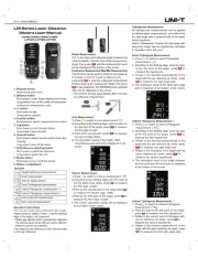
C. DC/AC Current Measurement (see figure 3)
figure 3
1.Press SELECT to switch AC or DC current measurement
2.Turn off power to the circuit before the connection
between the test leads across with the object being
measured.
3. Selecting the correct terminal input and turn the
rotary switch to select the measuring function. In case
of no any idea on the value input of the current, just
simply test from the high value to low one.
4. Fuses are located on mA and A terminal input. 10
Never attempt the test lead connect to any circuits
especially on the power supply terminal and may be
hurt.
5. For the safety purpose, less than seconds is 10
for each measurement duration and keep minutes 15
duration for next measurement during the current
measurement over 5A.
D. Resistance Measurement (see figure 4)
figure 4
1 -. The LCD displays “OL” indicating open circuit for
the tested resistor or the resistor value is higher than
the maximum range of the meter.
2. To maintain the resistance measurement accuracy,
discount circuit power and discharge all the high
voltage capacitors during the measuring resistance.
3. The test leads cause . ~ .2 resis tance 0 1Ω 0 Ω
variation during the measurement, In order to obtain
precision readings in istance measurement. low-res
Need to make the short circuit on the test leads and
mark the measurement value which show on LCD
display. Then deduct this variation value on the
measurement value which come the meter.
4. If reading with shortened test leads is not less Ω
than or equal to .5 , check for loose test leads, 0 Ω
incorrect function selection or others.
5. For sistance high-re measurement greater than
1MΩ, it is normal to take several seconds to obtain a
stable reading with short test leads for measurement.
6. 60V 30V Do not input higher than DC and AC rms
voltage to prevent any damage and accident.
E. Diodes Measurement (see figure 5)
figure 5
1. Disconnect circuit power and discharge all the high
voltage capacitors before measuring resistance.
2. Place the red test lead on the component’s anode
and place the back test lead on the component’s
cathode, a good diode should still produce a forward
voltage drop reading of ~ mV. The LCD 500 800
displays “OL” indicating circuit for the tested open-
diodes or the testing the diodes with polarity.
3. V. The open circuit for diodes is 1.5
4. Do not input higher than DC and AC rms 60V 30V
voltage to prevent any damage and accident.
F. Continuity Measurement (see figure 6)

Range Resolution Accuracy
400Ω 0.1Ω ±(1.2% + 2)
4KΩ 0.001KΩ
40kΩ 0.01kΩ ±(1% + 2)
400kΩ 0.1kΩ
4MΩ 0.001MΩ ±(1.2% + 2)
40MΩ 0.01MΩ ±(1.5% + 2)
Overload Protection: 500V AC/ DC
7. Diode, Continuity Test
Function Resolution Remark
0.001V Display positive voltage decline
r<10Ω buzze , >10Ω may or
may not buzzer
Overload Protection: 500V DC / AC.
8. Frequency and duty cycle
Range Resolution Accuracy
10Hz 0.01Hz ±
100Hz 0.1Hz
1KHz 0.001KHz
10KHz 0.01KHz (0.5%+3)
100KHz 0.1KHz
1MHz 0.001MHz
10MHz 0.01MHz
0.1~99.9% 0.1% For refer only
9. Temperature Measurement(For UT136C only)
Range Resolution Accuracy
-40~0℃ -(8% +5)
0~400℃ 1℃ ±(2.5%+3)
400~1000℃ ±(3% +3)
Overload Protection: 500V DC /AC.
Enclosed point contact K type thermocouple can
on ly e us ed o n le ss t han 23 0b℃ temper atu re
measurement.
10. NCV (For UT136D only)
Function Range Remarks
<10mm: buzzer beeps
NCV 220V/50Hz 10~50mm: may and may not beeps
>50mm: Buzzer not sound
Maintenance And Service
Warning
Make sure the test leads take off the terminal and the
circuit as well as power off the meter if want to open
the meter cover.
1.General Service and Maintenance
Periodically wipe the case with a damp cloth and mild
detergent. Do not use abrasives or solvents.
Any normal on the meter, stop use the meter and ab
return to service center.
When need to have cali ration on the mebter, please
allow certi ed engineer or speci c service center for fi fi
the service maintenance.
2. LCD display “ ” sign indicating will battery be
run out and need to replace a new y, if fail to do batter
that. It causes the variance of the measuring result.
Battery Specification: 9V 6F22 or NEDA 1604 /
IEC6LR61
Operating Steps:
(1) Turn the power in “ off "situation, then remove the
test lead out of the meter.
(2) Use screwdriver to take off the screw on the
b battery cover. Then you can take off old attery for
replacing.
(3) User screwdriver to take off two pieces of screws,
then you can re pla cing the urne d fu se(s) as b
replacement.
Fuse specification:
F1 Fuse φ5×20mm, F 0.5 A H 250V
F2 Fuse φ5×20mm, F 10 A H 250V
figure 6
1. Place the test leads to the circuit which be tested,
if etween oth terminals show resistance >100 . it b b Ω
is a short-circuit, no r. if terminals buzze between both
show resistance 10 , it is a good connection with ≤ Ω
continually u er. if etween oth t minals show b zz b b er
resistance> 10Ω, may or may not buzzer.
2. Resistance value on tested circuit display on LCD.
Unit is Ω.
Note:
1. To maintain the diodes measurement accuracy
disconnect circuit power and discharge all the high
voltage capacitors before the measuring.
2. For the continuity testing, the open circuit for
voltage is 0.5V.
3. Do not input higher than DC 60V and AC 30V rms
voltage to prevent any damage and accident.
G. Frequency and Duty Cycle Measure
ment (see
figure 7)
figure 7
1. Connect the test leads across with the object being
measured. The measured value shows on the display.
2.If you need to measure duty cycle, press SELECT
button to select % measurement mode.
Note:
Input Amplitude: a
When ≤100K Hz: a > 300 mV rms
When >100K Hz: a > 600 mV rms
Never input higher than 10V rms for test frequency
and duty cycle.
H. Temperature Measurement ( only UT136C, see
figure 8)
figure 8
1. Turn rotary switch to“℃”.
2. Put the multiple purpose socket into the correct
t minal. K-Type point contact temperature pro e er b
can only used in the measurement 230be below ℃,
if you want to measure over 230℃, you need to
separately buy another temperature probe
3. The LCD displays “OL” indicating point contact
temperature which take off. When short circuit probe
between ℃ terminal and COM t minal, the meter er
show the value of room temperature.
I. NCV Function ( UT136D only, see figure 9)
figure 9
1. Set the rotary switch to NCV and remove the test
lead from the input terminals.
2. Place the housing front part with marking towards
the 220V/50H eing measured. Distance <10mm, z b
the m mm<Distance <50mm, the meter eter buzzer; 10
may or may not Distance >50mm, the meter buzzer;
not buzzer and the LCD displays “OL”.
UT136A/B/C/D Operating Manual
Accuracy Specifications
Accuracy: ±(a% reading + b digits),guarantee for 1 year
Operating temperature: 23
℃±5℃
Relative Humidity: <75%
1. DC Voltage
Range Resolution Accuracy
400mV 0.1mV ±(0.8% + 3)
4V 0.001V
40V 0.01V ±(0.8% + 1)
400V 0.1V
500V 1V
Input impedance: all range 10MΩ
Maximum input voltage: 500V AC/DC.
2. AC Voltage
Range Resolution Accuracy
400mV 0.1mV ±(1.2% + 5)
4V 0.001V
40V 0.01V ±(1.2% + 3)
400V 0.1V
500V 1V
Input peda nce: a out 10M Maximum inp ut im b Ω;
voltage: 500V AC/DC
Frequency:40Hz~400Hz
Display effective value of sine wave( average value)
each measurement is applic from 5% of range as able
reference.
3. Capacitance (UT136B only)
Range Resolution Accuracy
4nF 0.001nF For refer only
40nF 0.01nF
400nF 0.1nF ±(4% + 3)
4μF 0.001μF
40μF 0.01μF
100μF 0.1μF ±(5% + 10)
Overload Protection: 500V AC / DC
4. DC Current
Range Resolution Accuracy
400μA 0.1μA
4000μA 1μA
40mA 0.01mA
400mA 0.1mA
4A 0.001A
10A 0.01A
Overload Protection:
mA range: F1 fuse φ5×20mm, F 0.5 A H 250V
10A range: F2 fuse φ5×20mm, F 10A H 250V
When 5A Continuous measurement is allowed, ≤
When <5A Continuous measurement less than 10
seconds at an interval more than 15 minutes.
5. AC Current
Range Resolution Accuracy
400μA 0.1μA
4000μA 1μA
40mA 0.01mA
400mA 0.1mA
4A 0.001A
10A 0.01A
Overload Protection:
mA range: F1 fuse φ5×20mm, F 0.5 A H 250V
10A range: F2 fuse φ5×20mm, F 10A H 250V
When 5A Continuous measurement is allowed, ≤
When > 5A Continuous measurement less than 10
seconds at an interval more than 15 minutes.
Frequency:40Hz~400Hz
Display effective value of sine wave( average value)
each measurement is applic from 5% of range as able
reference.
6. Resistance
±(1% + 2)
±(1.2% + 3)
±(1.5% + 5)
±(1.2% + 5)
±(1.5% + 3)
±(2% + 3)
0.1Ω
P/N: 110401103485X
MAY.2018 REV. 1
Product specificaties
| Merk: | Uni-T |
| Categorie: | Multimeter |
| Model: | UT136D |
Heb je hulp nodig?
Als je hulp nodig hebt met Uni-T UT136D stel dan hieronder een vraag en andere gebruikers zullen je antwoorden
Handleiding Multimeter Uni-T
11 Augustus 2025
3 April 2025

3 April 2025

3 April 2025
3 April 2025
3 April 2025

3 April 2025

3 April 2025

3 April 2025

3 April 2025
Handleiding Multimeter
- Abus
- Sonel
- Skandia
- Horex
- Weidmüller
- Hubinont
- Altai
- Yato
- Rohde & Schwarz
- Noyafa
- Mastech
- Ideal
- Wago
- Draper
- Etekcity
Nieuwste handleidingen voor Multimeter
8 September 2025

8 September 2025
8 September 2025
1 September 2025

1 September 2025
30 Augustus 2025
25 Augustus 2025

25 Augustus 2025
14 Augustus 2025
14 Augustus 2025