Planet POE-175-95 Handleiding
Planet Niet gecategoriseerd POE-175-95
Bekijk gratis de handleiding van Planet POE-175-95 (2 pagina’s), behorend tot de categorie Niet gecategoriseerd. Deze gids werd als nuttig beoordeeld door 148 mensen en kreeg gemiddeld 4.0 sterren uit 9 reviews. Heb je een vraag over Planet POE-175-95 of wil je andere gebruikers van dit product iets vragen? Stel een vraag
Pagina 1/2
- 1 -
- 2 -
- 3 -
- 4 -
- 5 -
- 6 -
- 7 -
- 8 -
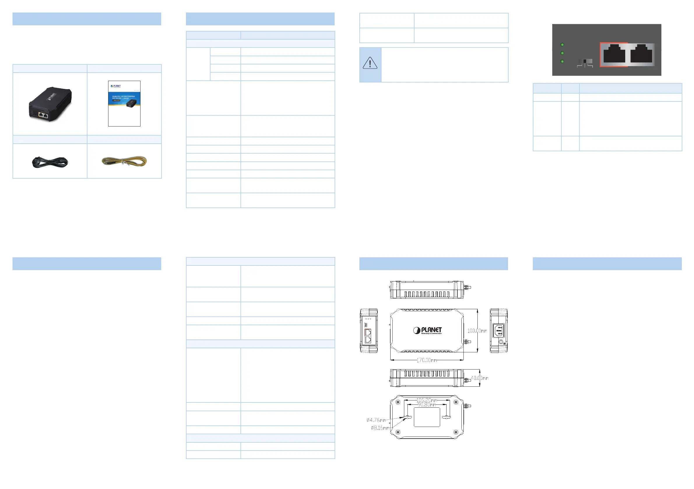
1. Package Contents
Thank you for purchasing PLANET POE-175-95 Single-port
10/100/1000Mbps 802.3bt PoE++ Injector.
Please unpack the box of the device carefully, and the box should
contain the following items:
802.3bt PoE injector x 1User’s manual x 1
AC power cord x 1Ground cable x 1
If any item is found missing or damaged, please contact your local
reseller for replacement.
3.ProductSpecications
ProductPOE-175-95
Hardware Specications
Interface
Input Port1 x RJ45 STP Data In
Output Port1 x RJ45 STP PoE (Data + Power) Out
AC Socket1 x AC input socket
DIP SwitchBT, UPoE or Legacy BT Mode
Network Cable
Twisted-pair cable up to 100 meters
(328ft)
10BASE-T: 4-pair UTP Cat. 3, 4, 5, 5e, 6
100BASE-TX: 4-pair UTP Cat. 5, 5e, 6
1000BASE-T: 4-pair UTP Cat. 5e, 6
LED Indicators
PWR x 1 (Green)
PoE-in-Use x 1 (Green)
PoE Max x 1 (Green)
Data Rate10/100/1000Mbps
Dimensions (W
x
D
x
H)170 x 100 x 40 mm
Weight443g
Unit Output VoltageDC 54V
Power RequirementsAC 100-240V, 1.8A max.
Power Consumption
Max. 1 watts/3.41 BTU (No Loading)
Max.111 watts/378.5 BTU (Full loading)
No. of Devices that
Can be Powered
1
LED Indicators:
10/100/1000T
EthernetEthernet+DC
PWR
PoE-in-Use
PoE Max.
POE-175-95
802.3bt PoE++ Injector
BTLegacy BTUPoE
LEDColorFunction
PWRGreenLights to indicate the device has power.
PoE-in-UseGreen
Lights There is a PoE PD connected to the
port, which supplies power.
Blinks Indicates the port’s power supply is
abnormal.
O No PoE powered device (PD) connected.
Max. PoE
Usage
Green
Lights Indicating the output power reaches
80%
Operating Humidity
5 ~ 90%, relative humidity,
non-condensing
Storage Humidity
5 ~ 90%, relative humidity,
non-condensing
Caution
1. As IEEE 802.3bt device provides high power, please
use high-quality network cable and RJ45 connector.
2. The maximum PoE output power depends on the
cable length and the quality of cable.
2. Product Features
Interface
2 RJ45 interfaces
1-port Data input
1-port Data + Power output
1 AC 100-240V input power socket
1 DIP switch for selecting BT, UPoE or Legacy mode
Power over Ethernet
Complies with IEEE 802.3af/at/bt PoE end-span/mid-span PSE
Supports PoE power up to 95 watts for PoE port
Auto-detection of PoE IEEE 802.3af/at/bt devices that may be
damaged by incorrect installation
Monitor the status of the total PoE usage in real time
Remote power feeding up to 100m
Hardware
All-in-one compact size design
Internal power supply
LED indicators for power, PoE-in-Use and maximum PoE usage
Power over Ethernet
PoE DIP Switch
IEEE 802.3af/at/bt PSE
UPoE
Legacy BT
PoE Power Output
Budget
DC 54V / 95-watt PoE via 4-pair
PoE Power Output
Max. 95W@1 m cable
Max. 73W@100 m cable
PoE Power Supply TypeEnd-span + Mid-span
Power Pin Assignment
Pair 1 End-span: 1/2 (-), 3/6 (+)
Pair 2 Mid-span: 4/5 (+), 7/8 (-)
Standards Conformance
Standards Compliance
IEEE 802.3 10BASE-T Ethernet
IEEE 802.3u 100BASE-TX Fast Ethernet
IEEE 802.3ab 1000BASE-T Gigabit
Ethernet
IEEE 802.3bt 4-pair Power over Ethernet
Type 4
IEEE 802.3at Power over Ethernet Plus
IEEE 802.3af Power over Ethernet
Regulatory ComplianceFCC Part 15 Class A, CE
Surge Protection
Dierence Mode: ±2KV,
Common mode: ±4KV
Electrostatic standardContact 6KV, air 8KV
Environment
Operating Temperature0 ~ 50 degrees C
Storage Temperature-40 ~ 70 degrees C
4. Product Outlook
100-240V AC, 50/60Hz
10/100/1000T
EthernetEthernet+DC
PWR
PoE-in-Use
PoE Max.
POE-175-95
802.3bt PoE++ Injector
BTLegacy BTUPoE
Figure 1: Dimensions
5. Hardware Installation
The following section describes the hardware features of the
POE-175-95. Before connecting any network device to it, please
read this chapter carefully.
5.1 PoE Injector Grounding
A good grounding system is the groundwork for the smooth and
safe operation of the POE-175-95, and an excellent way to prevent
lightning strikes and resistance to interference. Please follow the
POE-175-95’s grounding specication instructions to ensure a good
grounding system.
Proper Grounding
When using an AC power source, the device must be grounded
with the green and yellow ground cables; otherwise, shock hazards
may occur when insulation resistance between the internal power
supply and the PoE Injector degrades.
Lightning and Grounding Protection
The lightning protection system is an independent system
consisting of a lightning rod, conductor and connection joint with
the grounding system. The grounding system usually is shared
with the ground reference, and green and yellow ground cables.
Lightning and grounding protection is a building requirement, not a
specic requirement of the PoE Injector.
The POE-175-95 provides chassis grounding post on its rear side.
Chassis grounding protection should be properly connected to the
grounding connector.
Product specificaties
| Merk: | Planet |
| Categorie: | Niet gecategoriseerd |
| Model: | POE-175-95 |
| Kleur van het product: | Zwart |
| Gewicht: | 480 g |
| Breedte: | 170 mm |
| Diepte: | 100 mm |
| Hoogte: | 40 mm |
| LED-indicatoren: | Ja |
| Aantal Ethernet LAN (RJ-45)-poorten: | 1 |
| Ingangsspanning: | 100 - 240 V |
| Bekabelingstechnologie: | 10/100/1000Base-T(X) |
| Netwerkstandaard: | IEEE 802.3bt |
| Uitgangsvermogen: | 95 W |
| Temperatuur bij opslag: | -10 - 70 °C |
| Power LED: | Ja |
| Luchtvochtigheid bij opslag: | 5 - 90 procent |
| Spanning: | DC 54 V |
| Power over Ethernet (PoE): | Ja |
| RJ-45 uitgang ports: | 1 |
| RJ-45 invoer ports: | 1 |
| Bedrijfstemperatuur (T-T): | 0 - 50 °C |
| Relatieve vochtigheid in bedrijf (V-V): | 5 - 90 procent |
| Kabel standaard: | Cat6 |
Heb je hulp nodig?
Als je hulp nodig hebt met Planet POE-175-95 stel dan hieronder een vraag en andere gebruikers zullen je antwoorden
Handleiding Niet gecategoriseerd Planet

13 Mei 2026
13 Mei 2026
12 Mei 2026
7 Mei 2026
6 Mei 2026
6 Mei 2026
4 Mei 2026
6 Maart 2026
4 Maart 2026
31 December 2026
Handleiding Niet gecategoriseerd
Nieuwste handleidingen voor Niet gecategoriseerd
8 Juni 2026
8 Juni 2026
8 Juni 2026
8 Juni 2026
8 Juni 2026
8 Juni 2026
8 Juni 2026
8 Juni 2026
8 Juni 2026
8 Juni 2026