Planet LN1152 Handleiding
Planet Niet gecategoriseerd LN1152
Bekijk gratis de handleiding van Planet LN1152 (2 pagina’s), behorend tot de categorie Niet gecategoriseerd. Deze gids werd als nuttig beoordeeld door 9 mensen en kreeg gemiddeld 5.0 sterren uit 5 reviews. Heb je een vraag over Planet LN1152 of wil je andere gebruikers van dit product iets vragen? Stel een vraag
Pagina 1/2
- 1 -
- 2 -
- 3 -
- 4 -
- 5 -
- 6 -
- 7 -
- 8 -
1. Package Contents
Thank you for purchasing PLANET Industrial LoRa Node Controller,
LN series. The descriptions of these models are as follows:
LN501Outdoor IP67 LoRa Node Controller with Solar Panel
LN1152Indoor IP30 LoRa Node Controller
“LoRa Node” is used as an alternative name in this Quick
Installation Guide.
Open the box of the LoRa Node and carefully unpack it. The box
should contain the following items:
LN501LN1152
LoRa Node Controller x 1
Quick Installation Guide x 1
Data Cables x 2
Mounting Bracket x 1
Wall Mounting Kits x 1
Hose Clamps x 2
2550 mAh Battery x 2
LoRa Node Controller x 1
Quick Installation Guide x 1
LoRa Antenna x 1
12-Pin Terminal Block x 1
Wall Mounting Screws x 2
Power Adapter x 1
If any item is found missing or damaged, please contact your local
reseller for replacement.
Caution
1. Never put batteries in mouth. If swallowed, contact
your physician or local poison control center.
2. Do not short circuit; may cause burns or catch fire.
3. Batteries should not be exposed to excessive heat
such as sunshine, fire or the like.
3. Hardware Installation
Refer to the illustration and follow the simple steps below to
quickly install your LoRa Node.
3.1 LN501
3.1.1 Remove cover for setting analog input or power
output
When changing the analog input or power output of LN501 via DIP
switch, follow the steps below:
Step 1:Removethescrewcapsandtakeotheroofcover.
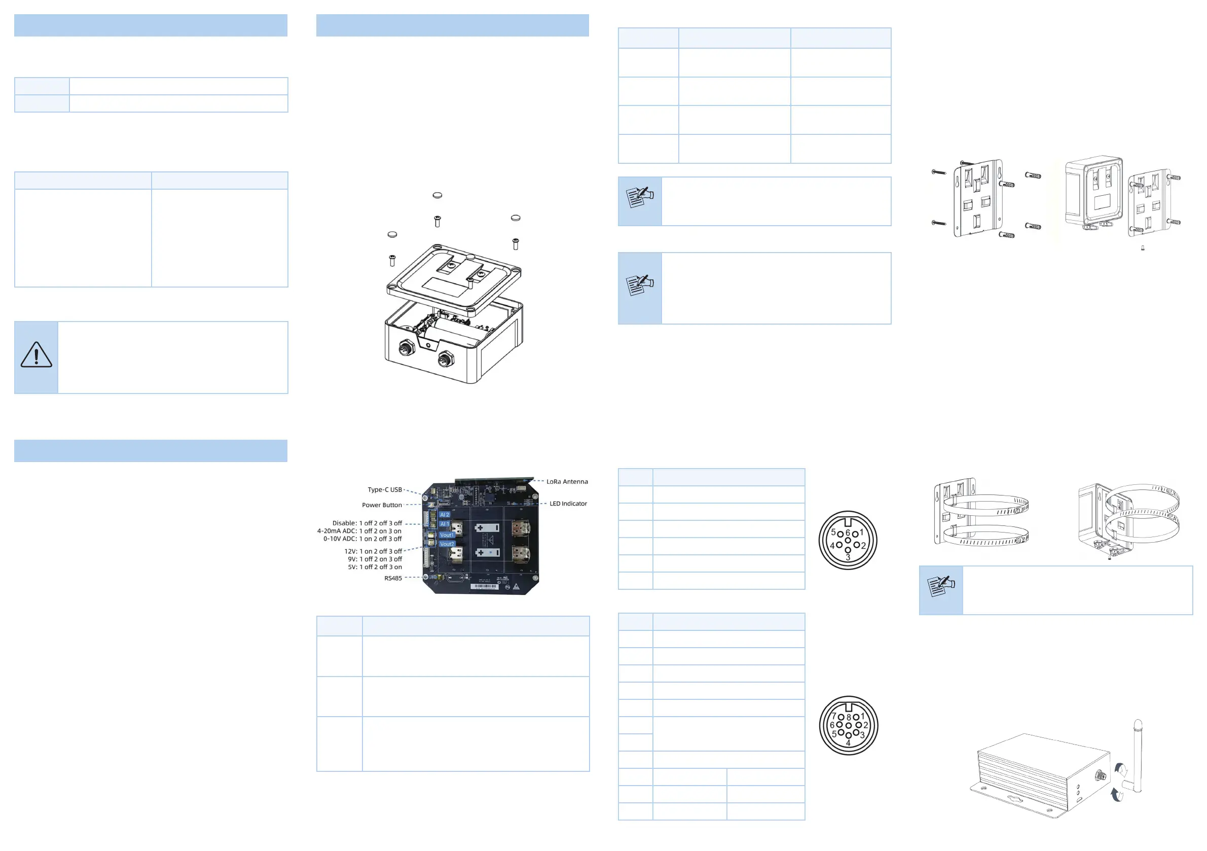
3.1.3 Wall Mounting
Make sure you have a wall mounting bracket, bracket mounting
screws, wall plugs, wall mounting screws and other required tools.
Step 1:Mark the four holes on the wall you prefer to place the
device and drill the marked four holes for the wall plugs
(anchors). Then place the mounting bracket over the
holes with the wall plugs inside, and tighten it with the
screws.
Step 2: Place the device on the mounting bracket and put the
small screw into the hole found on the bottom of the
deviceandthentightenthescrewtonishthejob.
3.1.4 Pole Mounting
Step 1:Straighten out the clamp and slide it through the
rectangular rings in the mounting bracket, and wrap the
clamp around the pole. Then use a screwdriver to tighten
the clamp by turning it clockwise.
Power Button:
FunctionActionLED Indication
Turn On
Press and hold the button
for more than 3s.
O On
TurnO
Press and hold the button
for more than 3s.
On O
Reset
Press and hold the button
for more than 10s.
Blinks.
CheckOn/O
Status
Quickly press the power
button.
Light On: Device is on.
LightO:Deviceiso.
Note
Please turn off the device before changing DIP
switches.
Step 3:Put back the roof cover and screw the screws.
Note
1. Analog input is set to 4-20mA by default; power
output is set to 12V by default.
2. Power output on interface 1 is used for powering
serial port devices and power output on interface 2
is used for powering analog devices.
2. Requirements
Workstations running Windows 10/XP/2003/Vista/7/8/2008.
Type C USB cable for LN501.
Micro USB cable for LN1152.
Step 2:Choose or change an analog input and power output via
DIP switch.
DIP Switch:
InterfaceDIP Switch
Power
Output
12V:1on2o3o(default)
9V:1o2on3o
5V:1o2o3on
Analog
Input
Disable:1o2o3o
4-20mAADC:1o2on3on(default)
0-10VADC:1on2o3o
RS485
Disable:1o2o3o(default)
Add120ΩresistorbetweenAandB:1on2o3o
Add1kΩpull-upresistoronA:1o2on3o
Add1kΩpull-downresistoronB:1o2o3on
3.1.2 Data Interface
Data Interface 1
PinDescription
15V/9V/12V OUT (Switchable)
23.3V OUT
3GND
4Analog Input 1
5Analog Input 2
65-24V DC IN
Data Interface 2
PinDescription
15V/9V/12V OUT (Switchable)
23.3V OUT
3GND
4GPIO1
5GPIO2
6
RS232/RS485 (Switchable)
7
8Reserved
PINRS232RS485
6TxA
7RxB
Step 2: Place the device on the mounting bracket and put the
small screw into the hole found on the bottom of the
deviceandthentightenthescrewtonishthejob.
Note
Please make sure the screws are tightly fixed.
3.2 LN1152
3.2.1 Antenna Installation
Step 1:Rotate the antenna into the antenna connector
accordingly.
Step 2:The external LoRa antenna should be installed vertically
for a good signal.
Product specificaties
| Merk: | Planet |
| Categorie: | Niet gecategoriseerd |
| Model: | LN1152 |
| Kleur van het product: | Zwart |
| Breedte: | 79 mm |
| Diepte: | 60 mm |
| Hoogte: | 24 mm |
| Gebruikershandleiding: | Ja |
| Internationale veiligheidscode (IP): | IP30 |
| LED-indicatoren: | Activity, System |
| Stroom: | 3 A |
| Montagewijze: | Bureaublad/wandmontage |
| Snelstartgids: | Ja |
| DC voltage input: | 3 - 24 V |
| Certificering: | CE, FCC |
| RS-232 port: | 1 |
| Duurzaamheidscertificaten: | CE, Federal Communications Commission (FCC) |
| Soort antenne: | Extern |
| Antennas quantity: | 1 |
| Relatieve luchtvochtigheid: | 0 - 95 procent |
| Spanning: | 30 V |
| Aansluiting antenne: | SMA |
| Ondersteunde protocollen: | Transparent (RS232), Modbus RTU (RS485) |
| Beheerplatform: | IN865, EU868, RU864 |
| Bedrijfstemperatuur (T-T): | -40 - 70 °C |
Heb je hulp nodig?
Als je hulp nodig hebt met Planet LN1152 stel dan hieronder een vraag en andere gebruikers zullen je antwoorden
Handleiding Niet gecategoriseerd Planet

13 Mei 2026
13 Mei 2026
12 Mei 2026
7 Mei 2026
6 Mei 2026
6 Mei 2026
4 Mei 2026
6 Maart 2026
4 Maart 2026
31 December 2026
Handleiding Niet gecategoriseerd
Nieuwste handleidingen voor Niet gecategoriseerd
8 Juni 2026
8 Juni 2026
8 Juni 2026
8 Juni 2026
8 Juni 2026
8 Juni 2026
8 Juni 2026
8 Juni 2026
7 Juni 2026
7 Juni 2026