Planet IXT-705AT Handleiding
Planet Niet gecategoriseerd IXT-705AT
Bekijk gratis de handleiding van Planet IXT-705AT (2 pagina’s), behorend tot de categorie Niet gecategoriseerd. Deze gids werd als nuttig beoordeeld door 49 mensen en kreeg gemiddeld 4.1 sterren uit 5 reviews. Heb je een vraag over Planet IXT-705AT of wil je andere gebruikers van dit product iets vragen? Stel een vraag
Pagina 1/2
- 1 -
- 2 -
- 3 -
- 4 -
- 5 -
- 6 -
- 7 -
- 8 -
1. Package Contents
Thank you for purchasing PLANET Industrial 10G Media Converter.,
In the following section, unless specied, the term “Industrial
Media Converter”mentioned in this manual refers to the
IXT-705AT.
Open the box of the Industrial Media Converter and carefully
unpack it. The box should contain the following items:
Industrial Media
Converter x 1
User’s Manual x 1DIN-rail Kit
Wall-mount KitSFP+ Dust Cap x 1RJ45 Dust Cap x 1
If any of these are missing or damaged, please contact your dealer
immediately; if possible, retain the carton including the original
packing material, and use them again to repack the product in case
there is a need to return it to us for repair.
2.ProductSpecications
ModelIXT-705AT
Hardware Specications
Copper
Interface
1 x 10000/5000/2500/1000/100 BASE-T RJ45
Auto-MDI/MDI-X, auto-negotiation
Fiber Optic
Interface
1 10GBASE-SR/LR SFP+ interface
Connector
Removable 6-pin terminal block
Pin 1/2 for Power 1, Pin 3/4 for fault alarm, Pin
5/6 for Power 2
Alarm
Provides one relay output for power failure
Alarm relay current carry capacity: 1A @ DC 24V
LED
System:
Fault Alert (Red), PWR (Green)
10000/5000/2500/1000/100 BASE-T RJ45
Interfaces
1/10G LNK (Orange)
5000/2500/100M LNK (Green)
ESD
Protection
6KV DC
EnclosureIP30 type metal case
InstallationDIN-rail kit and wall-mount ear
Dimensions
(WxDxH)
32 x 87 x 135mm
Weight458g
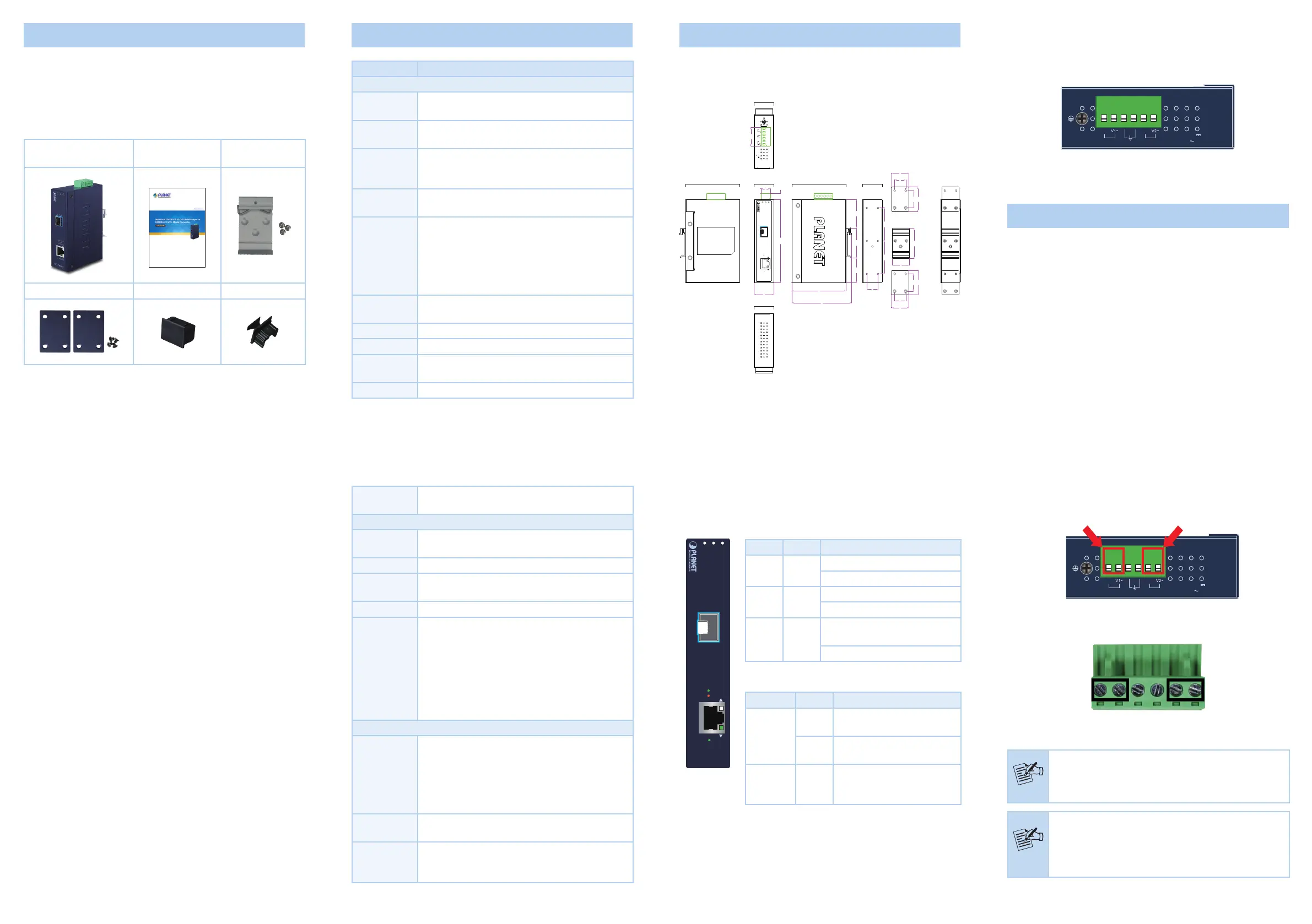
3.3 Converter Upper Panel
The upper panel of the IXT-705AT consists of one terminal block
connector within two DC power inputs. Figure 3-2 shows the upper
panel of the IXT-705AT.
Max. fault loading: 24V, 1A
V1+
V2+
PWR1
PWR2Fault
DC Input: 12-48V
, 0.6A max.
AC Input: 24V
, 0.2A max.
1 2 3 4 5 6
Figure 3-2: IXT-705AT Upper Panel
4. Hardware Installation
This section describes how to install the Industrial Media Converter
and makes connections to it. Please read the following sections and
perform the procedures in the order being presented.
This section describes the functionalities of the Industrial Media
Converter’s components and guides you to how to install it on
the DIN rail and wall. Basic knowledge of networking is assumed.
Please read this chapter completely before continuing.
4.1 Wiring the Power Inputs
The 6-contact terminal block connector on the top panel of
Industrial Media Converter is used for two DC redundant power
inputs. Please follow the steps below to insert the power wire.
3. Hardware Introduction
3.1 Physical Dimensions
IXT-705AT dimensions (W x D x H): 32 x 87 x 135mm
32.00
135.00
87.80
97.10
48.8046.5039.70
28.00
48.80
53.5053.50
18.00
15.20
30.00
9.20
40.00
28.0018.00
28.00
18.0028.00
28.00
40.00
Top View
Side ViewFront ViewSide View
Mounting Kit
Mounting Kit
DIN-Rail Kit
Unit: mm
Rear View
Bottom View
10G SFP+
10GBASE-T
IXT-705AT
2.5G
10G/1G
5G/100
FaultP2 P1
Max. fault loading: 24V, 1A
V1+
V2+
PWR1
PWR2Fault
DC Input: 12-48V
, 0.6A max.
AC Input: 24V
, 0.2A max.
1.1 Product Features
IXT-705AT Physical Port
1-port 10000/5000/2500/1000/100BASE-T RJ45 with auto
MDI/MDI-X function
1-port 10GBASE-X SFP+
Layer 2 Features
IEEE 802.3u/802.3ab/802.3bz/802.3ae Ethernet standard
compliant
Supports auto-negotiation and 100Mbps half/full duplex and
1/2.5/5/10Gbps full duplex mode
Prevents packet loss with back pressure (half-duplex) and
IEEE 802.3x pause frame ow control (full-duplex)
16K jumbo frame size support
Automatic address learning and address aging
Industrial Case and Installation
Slim-type IP30 metal case
DIN-rail or wall-mount design
Redundant power design
12 to 48V DC, redundant power with reverse polarity protection
AC 24V power adapter acceptable
Supports 6000 VDC Ethernet ESD protection
100 meters over Cat 6A at 10Gbps
-40 to 75 degrees C operating temperature
Plug and Play installation
Power
Requirements
DC 12~48V or 24V AC
Converter Specications
Flow Control
Back pressure for half duplex
IEEE 802.3x pause frame for full duplex
Fabric20Gbps
Address Table
9K entries, automatic source address learning and
aging
Jumbo Frame16K
Network
Cables
10000/5000/2500/1000/100 BASE-T:
Cat5e, 6, 6A, 7 UTP cable (100 meters, max.)
EIA/TIA-568 100-ohm STP (100 meters, max.)
10GBASE-LR/SR/BX:
50/125μm or 62.5/125μm multi-mode ber
optic cable, up to 300m
9/125μm single-mode ber optic cable, up to
60km
Standards Conformance
Standards
Compliance
IEEE 802.3u 100BASE-TX
IEEE 802.3ab 1000BASE-T
IEEE 802.3bz 2.5G/5GBASE-T
IEEE 802.3an 10GBASE-T
IEEE 802.3ae 10Gbps Ethernet
IEEE 802.3x full-duplex ow control
Regulatory
Compliance
FCC Part 15 Class A, CE
Stability
Testing
IEC60068-2-32 (Free fall)
IEC60068-2-27 (Shock)
IEC60068-2-6 (Vibration)
3.2 Converter Front Panel and LED Indicators
Figure 3-1 shows the front panels of the Industrial Media Converter.
10G SFP+
10GBASE-T
IXT-705AT
2.5G
10G/1G
5G/100
FaultP2 P1
Figure 3-1:
IXT-705AT
Front Panel
System
LEDColorFunction
P1Green
Lit: Power 1 is active
O: Power 1 is inactive
P2Green
Lit: Power 2 is active
O: Power 2 is inactive
FAULTRed
Lit: indicates either power 1 or
power 2 has no power.
O: No failure
Per 10000/5000/2500/1000/100BASE-T Port
LEDColorFunction
10/2.5/1G
Green
Lit: To indicate that the port
is operating at 2.5Gbps.
Orange
Lit: To indicate that the port
is operating at 10/1Gbps.
5G/100MGreen
Lit: To indicate that
the port is operating at
5Gbps/100Mbps.
1. Insert positive / negative DC power wires into Contacts 1 and 2
for power 1 or 5 and 6 for power 2.
Max. fault loading: 24V, 1A
V1+
V2+
PWR1
PWR2Fault
DC Input: 12-48V
, 0.6A max.
AC Input: 24V
, 0.2A max.
1 2 3 4 5 6
V1+V1-
V2+V2-
2. Tighten the wire-clamp screws for preventing the wires from
loosening.
123456
Power 1FaultPower 2
+-+-
Note
The wire gauge for the terminal block should be in the
range between 12 and 24 AWG.
Note
1. The DC power input range is 12V ~ 48V DC and
supports 24V AC.
2. Please just use one power input when using 24V
AC.
Product specificaties
| Merk: | Planet |
| Categorie: | Niet gecategoriseerd |
| Model: | IXT-705AT |
| Kleur van het product: | Blauw |
| Gewicht: | 458 g |
| Breedte: | 32 mm |
| Diepte: | 87 mm |
| Hoogte: | 135 mm |
| Materiaal behuizing: | Metaal |
| Internationale veiligheidscode (IP): | IP30 |
| LED-indicatoren: | Alarm, Fault, Link, Power |
| Connectiviteitstechnologie: | Bedraad |
| Aantal Ethernet LAN (RJ-45)-poorten: | 1 |
| Certificering: | FCC Part 15 Class A, CE |
| Plug and play: | Ja |
| Ingangsspanning: | 12 - 48 V |
| Ethernet LAN, data-overdrachtsnelheden: | 100,1000,2500,5000,10000 Mbit/s |
| Netwerkstandaard: | IEEE 802.3ab, IEEE 802.3ae, IEEE 802.3an, IEEE 802.3bz, IEEE 802.3u, IEEE 802.3x |
| Temperatuur bij opslag: | -40 - 75 °C |
| Intern: | Nee |
| Golflengte: | - nm |
| Luchtvochtigheid bij opslag: | 5 - 95 procent |
| Maximale overdrachtssnelheid van gegevens: | 20000 Mbit/s |
| Auto MDI/MDI-X: | Ja |
| Datastroombeheer: | Ja |
| Jumbo Frames ondersteuning: | Ja |
| Maximaal bereik: | 100 m |
| Bedrijfstemperatuur (T-T): | -40 - 75 °C |
| Relatieve vochtigheid in bedrijf (V-V): | 5 - 95 procent |
| Code geharmoniseerd systeem (HS): | 85176990 |
| Jumbo frames: | 16000 |
| DIN rail bevestiging: | Ja |
| Vezel-optische connector: | SFP+ |
| Duplex systeem: | Full, Half |
| Fibre channel-poorten: | 1 |
Heb je hulp nodig?
Als je hulp nodig hebt met Planet IXT-705AT stel dan hieronder een vraag en andere gebruikers zullen je antwoorden
Handleiding Niet gecategoriseerd Planet

13 Mei 2026
13 Mei 2026
12 Mei 2026
7 Mei 2026
6 Mei 2026
6 Mei 2026
4 Mei 2026
6 Maart 2026
4 Maart 2026
31 December 2026
Handleiding Niet gecategoriseerd
Nieuwste handleidingen voor Niet gecategoriseerd
8 Juni 2026
8 Juni 2026
8 Juni 2026
8 Juni 2026
8 Juni 2026
8 Juni 2026
8 Juni 2026
8 Juni 2026
7 Juni 2026
7 Juni 2026