Phoenix Contact QUINT-BUFFER/24DC/24DC/40 Handleiding
Phoenix Contact Niet gecategoriseerd QUINT-BUFFER/24DC/24DC/40
Bekijk gratis de handleiding van Phoenix Contact QUINT-BUFFER/24DC/24DC/40 (2 pagina’s), behorend tot de categorie Niet gecategoriseerd. Deze gids werd als nuttig beoordeeld door 120 mensen en kreeg gemiddeld 4.5 sterren uit 3 reviews. Heb je een vraag over Phoenix Contact QUINT-BUFFER/24DC/24DC/40 of wil je andere gebruikers van dit product iets vragen? Stel een vraag
Pagina 1/2
PORTUGUÊSE
PHOENIX CONTACT GmbH & Co. KG
Flachsmarktstraße 8, 32825 Blomberg, Germany
Fax +49-(0)5235-341200, Phone +49-(0)5235-300
MNR 9053500 - 01
www.phoenixcontact.com
Modulo buffer
In caso di guasto all'alimentazione, il modulo buffer consente di
continuare ad alimentare i carichi critici.
Caratteristiche
•Massima efficienza energetica
•Elevata affidabilità dell'impianto grazie alla lunga durata utile
del condensatore
•modulo UPS e batteria in un'unica custodia
Norme di sicurezza e avvertenze
Solo il personale specializzato può occuparsi dell'installaz., della
messa in servizio e del comando dell'apparecchio. Rispettare le
norme di sicurezza e antinfortunistiche nazionali.
Ulteriori informazioni sono disponibili nella scheda tecnica alla
pagina www.phoenixcontact.net/catalog.
•Il modulo buffer è un dispositivo da incasso.
•Montaggio orizzontale (morsetto input DC sotto).
•Rispettare i limiti meccanici e termici.
•Effettuate una connessione corretta e garantite la protezione
contro le scosse elettriche.
•Dimensionate e proteggete le linee in base alla corrente max.
di ingresso/uscita.
•Dopo l'installazione coprire il vano di connessione in modo da
evitare contatti delle parti sotto tensione (ad es. montaggio nel
quadro elettrico).
•Garantire una convezione sufficiente (5 cm sopra e sotto). La
custodia può diventare calda
•Il modulo buffer non richiede manutenzione. Solo il produttore
è autorizzato ad eseguire riparazioni.
Stato dei segnali:
Esempi di collegamento:
•Con disaccoppiamento tra ingresso e uscita (Fig.!5)
•Senza disaccoppiamento tra ingresso e uscita (Fig.!6)
Non lavorare mai in presenza di tensione.
Attenzione: danni elettrici
Per proteggere le linee inserite un fusibile
magnetotermico.
Estrarre i connettori solo in assenza di tensione.
Attenzione: Pericolo di morte a causa di scosse
elettriche!
Non lavorare mai in presenza di tensione.
508:
!Cavo in rame; temperatura di esercizio > 75 °C
(temperatura ambiente < 55 °C) e > 90 °C (temperatura
ambiente < 75 °C).
60950:
!Utilizzare capocorda per cavi flessibili.
Chiudere i vani morsetto non utilizzati.
LED Power Good (verde)
ONlampeggiaOFF
Segnale
Power Good
high
Segnale Power Good low
Funzionament
o normale
U
IN
= OKIl modulo
buffer viene
caricato
Il modulo
buffer è
caricato
Funzionament
o buffer
!Viene
assorbita
energia
Il modulo
buffer si
scarica
Module tampon
Le module buffer permet de poursuivre l'alimentation des
charges critiques en cas de défaillance de l'alimentation en
énergie.
Caractéristiques
•Efficacité énergétique maximale
•Disponibilité élevée des installations grâce à la durée de vie
prolongée des condensateurs
•Unité de commutation électronique et accumulateur d'énergie
combinés dans un seul boîtier
Consignes de sécurité et avertissements
Seul du personnel qualifié doit installer, mettre en service et
utiliser l'appareil. Les prescriptions nationales de sécurité et
prévention des accidents doivent être respectées.
Vous trouverez de plus amples informations dans la fiche
technique correspondante sur le site www.phoenixcontact.net/
catalog.
•Le module tampon est un appareil intégré.
•Montage horizontal (borne d'entrée DC en bas).
•Respecter les limites mécaniques et thermiques.
•Procéder au raccordement dans les règles de l'art et garantir la
protection contre l'électrocution.
•Dimensionner et protéger les câbles en fonction du courant
d'entrée/sortie max.
•Après installation, recouvrir la zone des bornes pour éviter tout
contact fortuit avec des pièces sous tension (par exemple,
montage en armoire).
•Garantir une convection suffisante (5 cm en haut et en bas). Le
boîtier peut s'échauffer
•Le module tampon ne requiert aucun entretien. Les
réparations ne peuvent être effectuées que par le fabricant.
État des signaux!:
Exemples de raccordement!:
•Avec découplage entrée/sortie (Fig.!5)
•Sans découplage entrée/sortie (Fig.!6)
Ne jamais travailler sur un module sous tension.
Attention : dommages électriques
Pour protéger les câbles, monter en amont un coupe-
circuit thermomagnétique.
Les conn. doivent uniquement être manipulés hors
tension.
Attention : danger de mort par choc électrique!!
Ne jamais travailler sur un module sous tension.
508:
!Câble en cuivre, température de service > 75 °C
(température ambiante < 55 °C) et > 90 °C (température
ambiante < 75 °C).
60950:
!Utiliser des embouts pour câbles flexibles.
Obturer les espaces de raccordement inutilisés.
LED Power Good (verte)
alluméeclignotedésactivé
Signal Power
Good High
Signal Power Good Low
Service
normal
U
IN
= OKModule buffer
en charge
Module buffer
chargé
Fonctionneme
nt buffer
!L'énergie est
prélevée
Le module
buffer est
déchargé
Buffer module
The buffer module enables continued supply of critical loads in
the event of a power supply malfunction.
Features
•Maximum energy efficiency
•High level of system availability due to high capacitor service
life
•electronic switchover unit and power storage device in one
housing
Safety notes and warning instructions
Only qualified specialists staff may install, set up and operate the
device. Observe the national safety rules and regulations for the
prevention of accidents.
For additional information, please refer to the corresponding data
sheet at www.phoenixcontact.net/catalog.
•The buffer module is a built-in device.
•Horizontal mounting (Input DC terminal block at the bottom).
•Observe mechanical and thermal limits.
•Establish connection correctly and ensure protection against
electric shock.
•Ensure cables are the correct size for the maximum input/
output current and have fuse protection.
•Following installation, cover the terminal area to prevent
accidental contact with live parts (e.g., installation in a control
cabinet).
•Ensure sufficient convection (5 cm above and below). The
housing can become hot.
•The buffer module is maintenance free. Repairs can only be
done by the manufacturer.
Signal states:
Connection examples:
•With decoupling between input/output (Fig.!5)
•Without decoupling between input/output (Fig.!6)
Never carry out work when voltage is present.
Attention: Electrical damage
Use an external thermomagnetic fuse for mains
protection.
Operate connectors only when there is no voltage applied.
Caution: Risk of electric shock
Never carry out work when voltage is present.
508:
!Copper cable; operating temperature > 75°C (ambient
temperature < 55°C) and > 90°C (ambient temperature <
75°C).
60950:
!Use ferrules for flexible cables.
Tighten screws on all unused terminals.
LED Power Good (green)
ONFlashingOFF
Power Good
signal high
Power Good signal low
Normal
operation
U
IN
= OKBuffer module
is being
charged
Buffer module
is charged
Buffer mode!Power is
being drawn
Buffer module
is discharged
Puffermodul
Das Puffermodul ermöglicht bei Störung der Energieversorgung
eine Weiterversorgung kritischer Lasten.
Merkmale
•Maximale Energieeffizienz
•Hohe Anlagenverfügbarkeit durch hohe
Kondensatorlebensdauer
•elektronische Umschalteinheit und Energiespeicher in einem
Gehäuse
Sicherheits- und Warnhinweise
Nur qualifiziertes Fachpersonal darf das Gerät installieren, in
Betrieb nehmen und bedienen. Nationale Sicherheits- und
Unfallverhütungsvorschriften sind einzuhalten.
Weitere Informationen finden Sie im zugehörigen Datenblatt
unter www.phoenixcontact.net/catalog.
•Das Puffermodul ist ein Einbaugerät.
•Montage waagerecht (Klemme Input DC unten).
•Mechanische und thermische Grenzen sind einzuhalten.
•Anschluss fachgerecht ausführen und Schutz gegen
elektrischen Schlag sicherstellen.
•Leitungen dem max. Eingangs-/Ausgangsstrom entsprechend
dimensionieren und absichern.
•Nach der Installation den Klemmenbereich abdecken, um
unzulässiges Berühren spannungsführender Teile zu
vermeiden (z. B. Einbau im Schaltschrank).
•Ausreichende Konvektion gewährleisten (5 cm oben und
unten). Gehäuse kann heiß werden
•Das Puffermodul ist wartungsfrei. Reparaturen sind nur durch
den Hersteller durchführbar.
Signalzustände:
Anschlussbeispiele:
•Mit Entkoppelung zwischen Ein-/Ausgang (Abb.!5)
•Ohne Entkoppelung zwischen Ein-/Ausgang (Abb.!6)
Niemals bei anliegender Spannung arbeiten.
Achtung: Elektroschäden
Zum Leitungsschutz, eine thermomagnetische Sicherung
vorschalten.
Steckverbinder nur spannungslos betätigen.
Vorsicht: Lebensgefahr durch Stromschlag!
Niemals bei anliegender Spannung arbeiten.
508:
!Kupferkabel; Betriebstemperatur > 75 °C
(Umgebungstemperatur < 55 °C) und > 90 °C
(Umgebungstemperatur < 75 °C).
60950:
!Aderendhülsen für flexible Kabel verwenden.
Ungenutzte Klemmräume schließen.
LED Power Good (grün)
anblinktaus
Power Good-
Signal high
Power Good-Signal low
NormalbetriebU
IN
= OKPuffermodul
wird geladen
Puffermodul
ist aufgeladen
Pufferbetrieb!Energie wird
entnommen
Puffermodul
ist entladen
QUINT-BUFFER/24DC/24DC/402320393
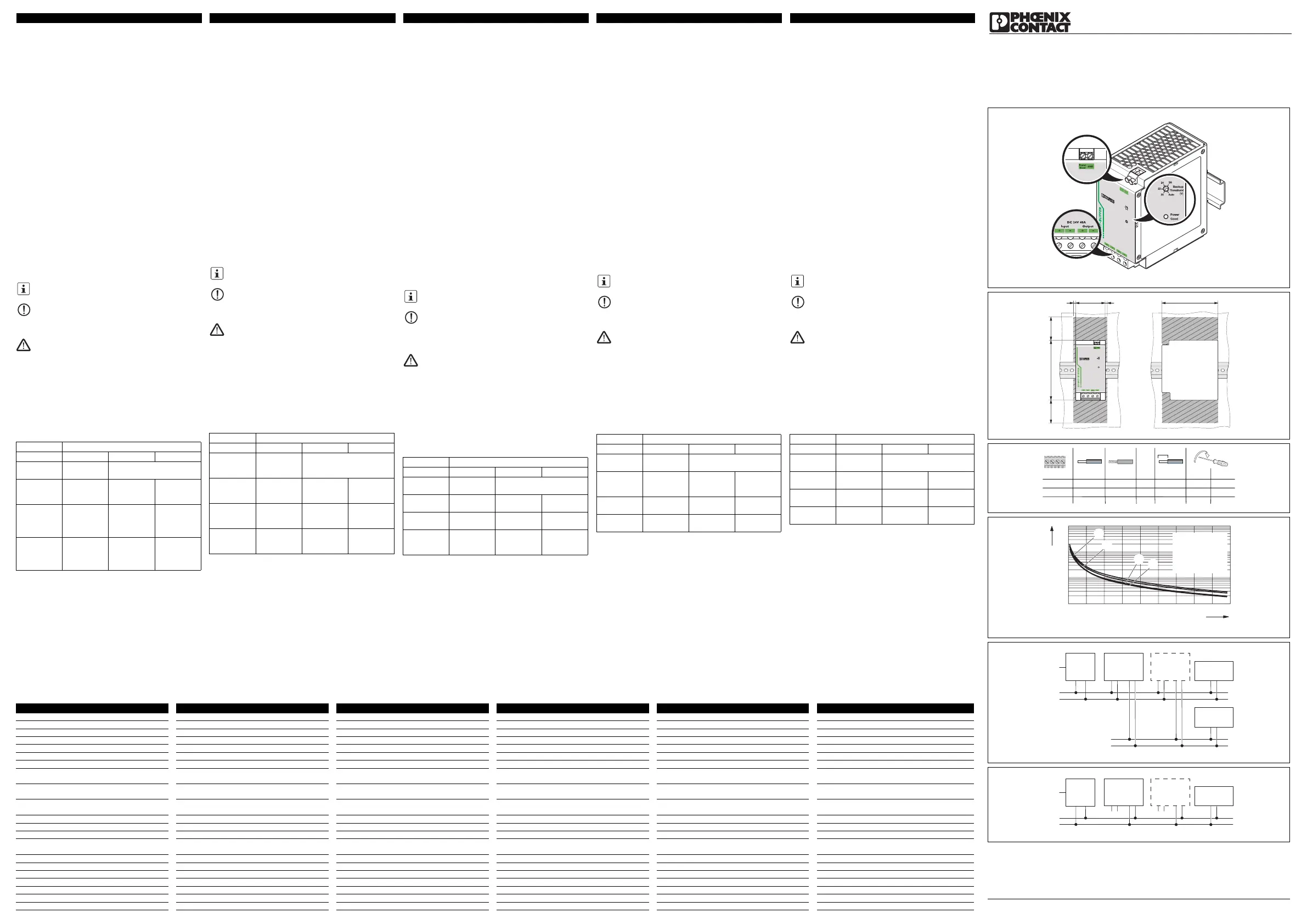
Abb./Fig. 1
Abb./Fig. 2
Abb./Fig. 3
Abb./Fig. 4
Abb./Fig. 5
Abb./Fig. 6
Backup
26
24
22
20
Auto
Threshold
[V]
Power
Good
Output
DC 24V 40A
Input
GND
Good
Power
125
24
22
20
Auto
[
V
]
26
Backup
Threshold
Power
Good
DC 24V 40A
Input
Output
64
5
5
50
50
130
AWG
20-6
L[mm]
10
[Nm][lb in]
1,2-1,5
10,6-13,3
Input
20-6
24-12
10
10
1,2-1,5
0,5-0,6
10,6-13,3
5-7
Output
Signals
[mm²]
0,5-16
[mm²]
0,5-10
0,5-16
0,2-25
0,5-10
0,2-25
= 29,0 V
= 18,5 V
= 27,5 V
= 22,5 V
0,1
1,0
10
100
051015202530354045
Load [A]
Buffer time [s]
QUINT
POWER
AC
++
+
--
-
DC
Unbuffered
Load
Buffered
Load
+
-
DC
QUINT
BUFFER
Input
++--
Output
QUINT
BUFFER
Input
++--
Output
Power
Supply
AC
+
-
DC
Buffered
Load
QUINT
BUFFER
Input
++--
Output
QUINT
BUFFER
Input
++--
Output
DE
DEUTSCHENGLISHFRANÇAISITALIANO
Einbauanweisung für den Elektroinstallateur
ENInstallation note for electrical personnel
FRInstructions d'installation pour l'électricien
ITIstruzioni di montaggio per l'elettricista installatore
2011-12-09
© PHOENIX CONTACT 2011
DNR 83114511
Módulo de bateria de energia
O módulo acumulador permite no caso de queda da energia
continuar a alimentação com energia de carga críticas.
Características
•Máxima eficiência energética
•Alta disponibilidade do sistema mediante elevada vida útil dos
condensadores
•reúne a unidade de comutação eletrônica e um módulo de
bateria de energia na mesma caixa
Instruções de segurança e alerta
O equipamento somente pode ser instalado, colocado em
funcionamento e operado por pessoal técnico qualificado.
Observar as normas de segurança e prevenção de acidentes
nacionais.
Outras informações encontram-se respectiva na ficha técnica em
www.phoenixcontact.net/catalog.
•O módulo do buffer é um aparelho de encastrar.
•Montagem horizontal (borne Input CC embaixo).
•Observar os limites mecânicos e térmicos.
•Executar conexão de rede profissional e garantir proteção
contra impacto.
•Dimensionar e proteger cabos conforme a máx. corrente de
entrada/saída.
•Após a instalação, cobrir a área de bornes, para evitar o
contato não permitido com peças energizadas (por ex.
instalação no quadro de comando).
•Garantir convecção suficiente (5 cm em cima e embaixo).
Caixa pode estar quente
•O módulo do buffer não necessita de manutenção. Consertos
somente podem ser efetuados pelo fabricante.
Estados de sinal:
Exemplos de conexão:
•Com entrada/saída desacopladas (Fig.!5)
•Com entrada/saída não desacopladas (Fig.!6)
Nunca trabalhe com tensão ligada.
Atenção: Danos elétricos
Para proteção da linha, instalar um fusível de pré-proteção
termomagnético.
Acionar conector de encaixe apenas sem tensão.
Cuidado: Perigo de morte devido à choque elétrico!
Nunca trabalhe com tensão ligada.
508:
!Cabo de cobre; temperatura operacional > 75 °C
(temperatura ambiente < 55 °C) e > 90 °C (temperatura
ambiente < 75 °C).
60950:
!Utilizar terminais tubulares para cabos flexíveis.
Fechar áreas de bornes não utilizadas.
LED "Power Good" (verde)
napiscandodesligado
Sinal "Power
Good" high
Sinal "Power Good" low
Operação
normal
U
IN
= OKMódulo
acumulador é
carregado
Módulo
acumulador
está
carregado
Operação
com bateria
!Energia está
sendo retirada
Módulo
acumulador
está
descarregado
PTInstrução de montagem para o eletricista
PNR 104438 - 01
Dados técnicosDati tecniciCaractéristiques techniquesTechnical dataTechnische Daten
Dados de entradaDati d'ingressoDonnées d'entréeInput dataEingangsdaten
Tensão nominal de entradaTensione d'ingresso nominaleTension d'entrée nominaleNominal input voltageNenneingangsspannung 24 V DC
Faixa de tensão de entradaRange tensione d'ingressoPlage de tensions d'entréeInput voltage rangeEingangsspannungsbereich 18 V DC ... 30 V DC
Consumo de energiaCorrente assorbitaCourant absorbéCurrent consumptionStromaufnahme0,1 A / 0,7 A / 44,7 A
Limite adicional (fixo, variável)Soglia di collegamento (fissa, variabile)Seuil de commutation (fixe, variable)Connect threshold (fixed, variable)Zuschaltschwelle (fix, variabel)< 20 V DC (< 22 V; < 24 V; < 26 V) , (U
IN
- 1 V) / 0,1 s
Tempo de bateriaTempo di riservaTemps de sauvegardeBuffer periodPufferzeit0,2 s (40 A) / 8 s (1 A)
Dados de saídaDati uscitaDonnées de sortieOutput dataAusgangsdaten
Tensão nominal de saída (de acordo com a tensão
de entrada)
Tensione nominale in uscita (in funzione della
tensione di ingresso)
Tension de sortie nominale (dépend de la tension
d'entrée)
Nominal output voltage (depending on the input
voltage)
Nennausgangsspannung (abhängig von der
Eingangsspannung)
24 V DC
Corrente de saída com resfriamento de convecçãoCorrente d'uscita con raffreddamento a convezioneCourant de sortie pour le refroidissement par
convection
Output current with convection coolingAusgangsstrom bei Konvektionskühlung40 A
Ligável em paralelosimPossibilità di collegamento in parallelosìMontage en parallèle autoriséouiConnection in parallelYesParallelschaltbarkeitja
Ligável em sérieNãoPossibilità di collegamento in serieNoConnectabilité en sérieNonConnection in seriesNoSerienschaltbarkeitnein
Máx. dissipação de energiaMax. potenza dissipataPuissance dissipée max.Max. power dissipationMax. Verlustleistung8 W
EficiênciaEfficienzaRendementDegree of efficiencyWirkungsgrad> 99 %
Dados GeraisDati generaliCaractéristiques généralesGeneral dataAllgemeine Daten
Tensão de isolamento entrada, saída/caixaTensione di isolamento ingresso, uscita/custodiaTension d'isolement entrée, sortie/boîtierInsulation voltage input, output / housingIsolationsspannung Eingang, Ausgang/Gehäuse500 V
Grau de proteção / Classe de proteçãoGrado di protezione / Classe di protezioneIndice de protection / Classe de protectionDegree of protection / Protection classSchutzart / SchutzklasseIP20 / III
DeratingDeratingDéclassementDeratingDerating60 °C ... 80 °C ( 2,5 %/K )
Grau de impurezasGrado d'inquinamentoDegré de pollutionPollution degreeVerschmutzungsgrad2
Temperatura ambiente (operação)Temperatura di utilizzo (Funzionamento)Température ambiante (Fonctionnement)Ambient temperature (operation)Umgebungstemperatur (Betrieb)-25 °C ... 80 °C
Temperatura ambiente (armazenamento/transporte)Temperatura ambiente (stoccaggio/trasporto)Température ambiante (stockage/transport)Ambient temperature (storage/transport)Umgebungstemperatur (Lagerung/Transport)-40 °C ... 85 °C
Umidade com 25 °C, sem condensaçãoUmidità a 25 °C, nessuna condensaHumidité à 25 °C, sans condensationHumidity at 25°C, no condensationFeuchtigkeit bei 25 °C, keine Betauung≤ 95 %
Dimensões (L / A / P) / + Trilho de fixaçãoDimensioni (L/A/P) / + Guida di supportoDimensions (l x H x P) / + profiléDimensions (W/H/D) / + DIN railAbmessungen (B/H/T) / + Tragschiene64 x 130 x 125 mm / 122 x 130 x 67 mm
PesoPesoPoidsWeightGewicht1,1 kg
Product specificaties
| Merk: | Phoenix Contact |
| Categorie: | Niet gecategoriseerd |
| Model: | QUINT-BUFFER/24DC/24DC/40 |
Heb je hulp nodig?
Als je hulp nodig hebt met Phoenix Contact QUINT-BUFFER/24DC/24DC/40 stel dan hieronder een vraag en andere gebruikers zullen je antwoorden
Handleiding Niet gecategoriseerd Phoenix Contact

26 Mei 2026
20 Mei 2026
19 Mei 2026
19 Mei 2026
9 April 2026
26 Maart 2026
25 Maart 2026
26 Februari 2026
19 Januari 2026
19 Januari 2026
Handleiding Niet gecategoriseerd
Nieuwste handleidingen voor Niet gecategoriseerd
23 Juli 2026
23 Juli 2026
23 Juli 2026
23 Juli 2026
23 Juli 2026
23 Juli 2026
23 Juli 2026
23 Juli 2026
23 Juli 2026
22 Juli 2026