Phoenix Contact PSR-PS21-1NO-1NC-24DC-SC Handleiding
Phoenix Contact Niet gecategoriseerd PSR-PS21-1NO-1NC-24DC-SC
Bekijk gratis de handleiding van Phoenix Contact PSR-PS21-1NO-1NC-24DC-SC (2 pagina’s), behorend tot de categorie Niet gecategoriseerd. Deze gids werd als nuttig beoordeeld door 107 mensen en kreeg gemiddeld 4.6 sterren uit 3 reviews. Heb je een vraag over Phoenix Contact PSR-PS21-1NO-1NC-24DC-SC of wil je andere gebruikers van dit product iets vragen? Stel een vraag
Pagina 1/2
PHOENIX CONTACT GmbH & Co. KG
Flachsmarktstraße 8, 32825 Blomberg, Germany
Fax +49-(0)5235-341200, Phone +49-(0)5235-300
phoenixcontact.com
DEBetriebsanleitung für den Elektroinstallateur
(Originalbetriebsanleitung)
ENOperating instructions for electrical personnel
(original operating instructions)
FRManuel d'utilisation pour l'électricien
(instructions de service originales)
NLBedieningshandleiding voor elektrotechnische installateurs
(originele bedieningshandleiding)
2015-03-10
© PHOENIX CONTACT 2015
Sicherheitsrelais
1.Inhalt der EG-Konformitätserklärung
Hersteller: PHOENIX CONTACT GmbH & Co.KG,
Flachsmarktstr.8, 32825 Blomberg, Germany
Das vorstehend bezeichnete Produkt stimmt mit den wesentlichen Anforderungen
der nachfolgenden Richtlinie(n) und deren Änderungsrichtlinien überein:
Für die Beurteilung der Übereinstimmung wurden folgende einschlägige Normen
herangezogen:
EN 61000-6-2:2005+AC:2005; EN61000-6-4:2007+A1:2011
EN50178:1997; EN60079-0:2012+A11:2013; EN60079-15:2010
Diese Erklärung bescheinigt die Übereinstimmung mit den wesentlichen
Anforderungen der genannten Richtlinie(n), enthält jedoch keine Zusicherung von
Eigenschaften.
Aussteller: Martin Müller, Head of Business Unit ION
2.Sicherheitshinweise:
•Beachten Sie die Sicherheitsvorschriften der Elektrotechnik und der
Berufsgenossenschaft!
•Werden die Sicherheitsvorschriften nicht beachtet, kann Tod, schwere
Körperverletzung oder hoher Sachschaden die Folge sein!
•Inbetriebnahme, Montage, Änderung und Nachrüstung darf nur von einer
Elektrofachkraft ausgeführt werden!
•Betrieb im verschlossenen Schaltschrank gemäß IP54!
•Schalten Sie das Gerät vor Beginn der Arbeiten spannungsfrei!
•Während des Betriebes stehen Teile der elektrischen Schaltgeräte unter
gefährlicher Spannung!
•Schutzabdeckungen dürfen während des Betriebes von elektrischen
Schaltgeräten nicht entfernt werden!
•Wechseln Sie das Gerät nach dem ersten Fehler unbedingt aus!
•Reparaturen am Gerät, insbesondere das Öffnen des Gehäuses, dürfen
nur vom Hersteller vorgenommen werden.
•Bei Erkennung eines Fehlers durch die übergeordnete Steuerung ist
davon auszugehen, dass die Sicherheitsfunktion nicht mehr ausgeführt
werden kann.
Die Fehlerbehebung muss innerhalb von 72Stunden erfolgen oder
innerhalb der Prozesssicherheitszeit, sofern die Applikation dieses
erfordert.
•Bewahren Sie die Betriebsanleitung auf!
2.1Installation in der Zone 2
•Das Gerät der Kategorie 3 ist zur Installation in dem explosionsgefährdeten
Bereich der Zone 2 geeignet. Es erfüllt die Anforderungen der EN60079-
0:2012+A11:2013 (IEC60079-0:20116thED.) und EN60079-15:2010
(IEC60079-15:20104thED.).
•Das Gerät ist in ein Gehäuse (Schalt- oder Verteilerkasten) einzubauen, dass
die Anforderungen der EN60079-15:2010 (IEC60079-15:20104th ED.) und
mindestens die Schutzart IP54 (EN/IEC60529) erfüllt.
•Das Gerät ist in einer Umgebung zu verwenden, die höchstens den
Verschmutzungsgrad 2 gemäß EN/IEC60664-1 aufweist.
•Beachten Sie bei der Installation und beim Anschluss der Versorgungs- und
Signalstromkreise die Anforderungen der EN/IEC60079-14.
•An Stromkreise in der Zone 2 dürfen nur Geräte angeschlossen werden, welche
für den Betrieb in der Ex-Zone 2 und die am Einsatzort vorliegenden
Bedingungen geeignet sind.
•Das Gerät ist an Versorgungsstromkreise anzuschließen, deren Nennspannung
nicht um 140% überschritten werden kann, verursacht durch transiente
Störungen.
•Schließen Sie keine Kabel/Leitungen innerhalb des explosionsgefährdeten
Bereiches an und trennen Sie dort auch keine Verbindungen auf, wenn diese
unter Spannung stehen.
•Das Gerät ist außer Betrieb zu nehmen und unverzüglich aus dem Ex-Bereich
zu entfernen, wenn es beschädigt ist, unsachgemäß belastet oder gelagert
wurde bzw. Fehlfunktionen aufweist.
2.2Staubexplosionsgefährdete Bereiche
3.Bestimmungsgemäße Verwendung
Relais zur sicheren Kopplung von digitalen Ausgangssignalen.
Mit Hilfe dieses Modules werden Stromkreise sicherheitsgerichtet unterbrochen.
4.Produktmerkmale
–1 Freigabestrompfad unverzögert
–1 Rückmeldestrompfad unverzögert
–1 digitaler Meldeausgang
–Integrierter Testpulsfilter
–Aktive Fehlerrückmeldung über A1
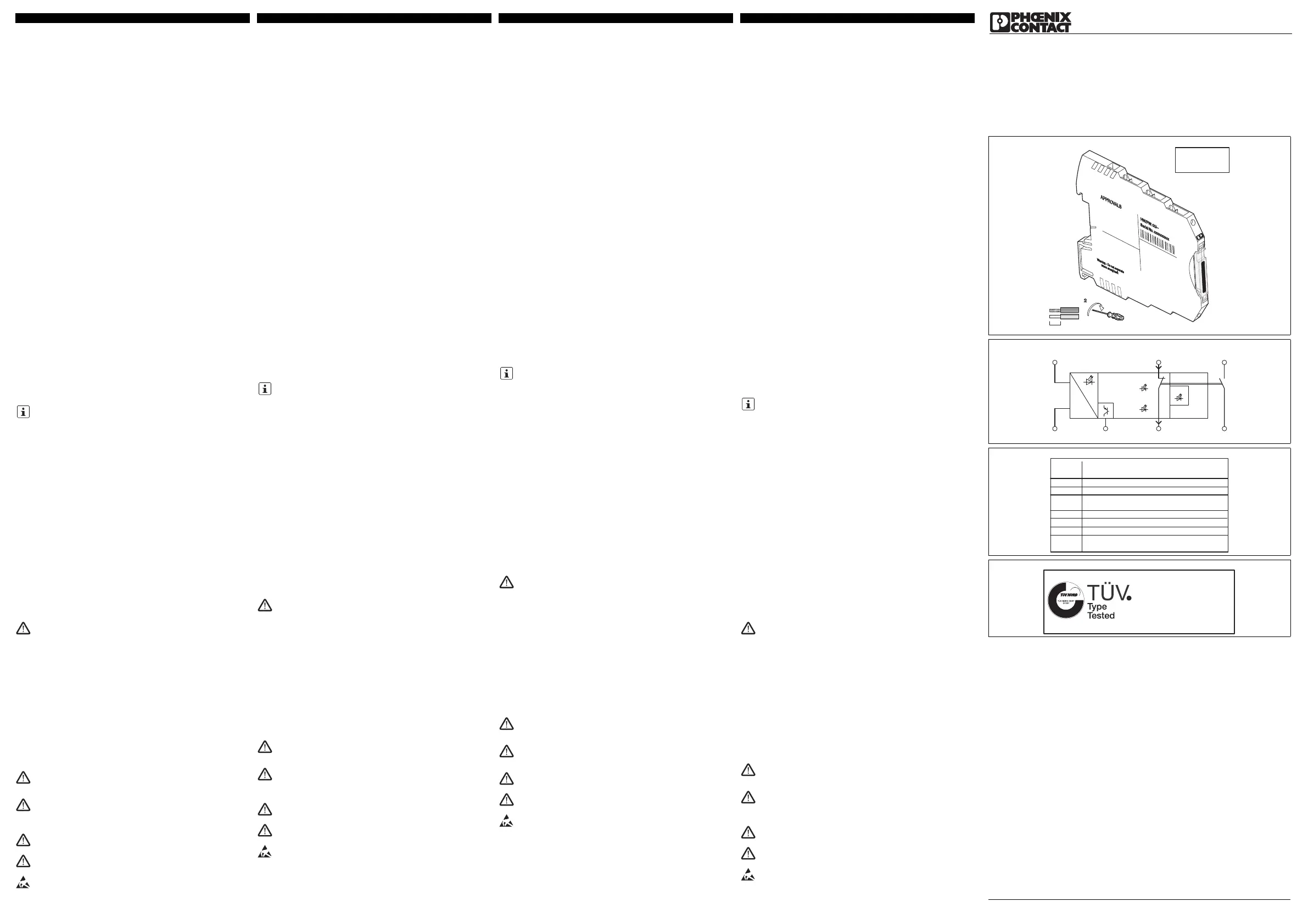
5.Anschlusshinweise
–Blockschaltbild ()
–Klemmpunktbelegung ( - )
Produktbezeichnung:Artikelnummer:
PSR-PS21-1NO-1NC-24DC-SC2700357
2004/108/EGEMV-Richtlinie (Elektromagnetische Verträglichkeit)
2006/95/EGNiederspannungsrichtlinie
94/9/EGEx-Richtlinie (ATEX)
Stellen Sie sicher, dass Sie immer mit der gültigen Dokumentation arbeiten.
Diese steht im Internet zur Verfügung unter phoenixcontact.net/products.
WARNUNG: Explosionsgefahr
Das Gerät ist nicht für den Einsatz in staubexplosionsgefährdeten
Atmosphären ausgelegt.
An induktiven Lasten ist eine geeignete und wirksame Schutzbeschaltung
vorzunehmen. Diese ist parallel zur Last auszuführen, nicht parallel zum
Schaltkontakt.
Bei dem Betrieb von Relaisbaugruppen ist vom Betreiber kontaktseitig die
Einhaltung der Anforderungen an die Störaussendung für elektrische und
elektronische Betriebsmittel (EN/IEC61000-6-4) zu beachten und ggf. sind
entsprechende Maßnahmen durchzuführen.
Setzen Sie ausschließlich Netzteile mit sicherer Trennung mit SELV/
PELV-Spannung nach EN 50178 / VDE0160 (SELV/PELV) ein.
Vermeiden Sie Magnetfelder mit einer Magnetfeldstärke >30A/m in der
Umgebung des Gerätes.
Treffen Sie Schutzmaßnahmen gegen elektrostatische Entladung!
Veiligheidsrelais
1.Inhoud van de EG-conformiteitsverklaring
Fabrikant: PHOENIX CONTACT GmbH & Co.KG,
Flachsmarktstr.8, 32825 Blomberg, Duitsland
Het hierboven beschreven product voldoet aan de belangrijkste eisen van de
volgende richtlijn(en) en de bijbehorende wijzigingsrichtlijnen:
Om te beoordelen of een product aan de betreffende eisen voldoet, worden de
volgende relevante normen gehanteerd:
EN 61000-6-2:2005+AC:2005; EN61000-6-4:2007+A1:2011
EN50178:1997; EN60079-0:2012+A11:2013; EN60079-15:2010
Deze toelichting bekrachtigt het feit dat een product aan de belangrijkste eisen van
de genoemde richtlijn(en), voldoet, maar vormt geen garantie voor de
eigenschappen.
Uitgever: Martin Müller, Head of Business Unit ION
2.Veiligheidsaanwijzingen:
•Neem de veiligheidsvoorschriften van de elektrotechniek en de
betreffende bedrijfsvereniging in acht!
•Worden de veiligheidsvoorschriften niet in acht genomen, dan kan dit de
dood, ernstig lichamelijk letsel of aanzienlijke materiële schade tot
gevolg hebben!
•De werkzaamheden voor inbedrijfstelling, montage, modificatie en
uitbreiding mogen uitsluitend door een elektrotechnicus worden
uitgevoerd!
•Bedrijf in gesloten schakelkast overeenkomstig IP54!
•Schakel het moduul voor aanvang van de werkzaamheden spanningsvrij!
•Tijdens bedrijf staan delen van de elektrische schakelapparatuur onder
gevaarlijke spanning!
•Beschermkappen mogen tijdens de werking van elektrische
schakelapparatuur niet worden verwijderd!
•Verwissel het moduul beslist na het optreden van de eerste fout!
•Reparaties aan het moduul, vooral het openen van de behuizing, mogen
uitsluitend door de fabrikant worden uitgevoerd.
•Als een fout wordt herkend door de hogere besturing, moet ervan
uitgegaan worden dat de veiligheidsfunctie niet meer uitgevoerd kan
worden.
Het verhelpen van storingen moet binnen 72uur plaatsvinden of binnen
de procesveiligheidstijd, voor zover de applicatie dit vereist.
•Bewaar de handleiding!
2.1Installatie in de zone 2
•Het apparaat van categorie 3 is geschikt voor installatie in de explosiegevaarlijke
omgeving van zone 2. Het voldoet aan de vereisten van EN60079-
0:2012+A11:2013 (IEC60079-0:20116thED.) en EN60079-15:2010
(IEC60079-15:20104thED.).
•Het apparaat moet in een behuizing (schakel- of verdelerkast) ingebouwd
worden die voldoet aan de eisen van EN60079-15:2010 (IEC60079-
15:20104th ED.) en minstens beschermmethode IP54 (EN/IEC60529) bezit.
•Het apparaat moet in een omgeving gebruikt worden die maximaal
vervuilingsgraad 2 volgens EN/IEC60664-1 bezit.
•Neem bij de installatie en bij de aansluiting van de voedings- en signaalcircuits
de vereisten van EN/IEC60079-14 in acht.
•Op de stroomcircuits in zone 2 mogen uitsluitend apparaten worden
aangesloten, die geschikt zijn voor toepassing in Ex-zone 2 en die geschikt zijn
voor de heersende omstandigheden op de plaats van installatie.
•Het apparaat dient aangesloten te worden op voedingscircuits waarvan de
nominale spanning de drempel van 140% niet kan overschrijden, veroorzaakt
door transiënte storingen.
•Sluit geen kabels/leidingen in een bereik aan waar explosiegevaar heerst en
koppel geen verbindingen af, als deze onder spanning staan.
•Wanneer het apparaat beschadigd is, onjuist is belast of opgeslagen resp. niet
correct functioneert, dient het buiten bedrijf te worden gesteld en onmiddellijk uit
de Ex-omgeving te worden verwijderd..
2.2Stofexplosiegevaarlijke bereiken
3.Voorgeschreven gebruik
Relais voor een veilige koppeling van digitale uitgangssignalen.
Met behulp van deze modulen worden stroomcircuits veiligheidsgericht
onderbroken.
4.Productkenmerken
–1 vrijgavecircuit, onvertraagd
–1 retourmeldcircuit, onvertraagd
–1 digitale meldingsuitgang
–Geïntegreerd testpulsfilter
–Actieve fout-retourmelding via A1
5.Aansluitaanwijzingen
–Blokschema ()
–Aansluitpuntbezetting ( - )
Productomschrijving:artikelnummer:
PSR-PS21-1NO-1NC-24DC-SC2700357
2004/108/EGEMC-richtlijn (elektromagnetische compatibiliteit)
2006/95/EGLaagspanningsrichtlijn
94/9/EGEx-richtlijn (ATEX)
Zorg dat u altijd de beschikking heeft over de geldige documentatie. U vindt
deze op internet: phoenixcontact.net/products.
WAARSCHUWING: explosiegevaar
Het apparaat is niet geschikt voor toepassing in stofexplosiegevaarlijke
omgevingen.
Bij inductieve belastingen dient een geschikte en effectieve
beveiligingsschakeling te worden gerealiseerd. Deze dient parallel aan de
belasting te worden uitgevoerd, niet parallel aan het schakelcontact.
Bij gebruik van relaismodulen dient de gebruiker aan de contactzijde
rekening te houden met de eisen die worden gesteld ten aanzien van de
stooremissie bij elektrische en elektronische bedrijfsmiddelen (EN/
IEC61000-6-4) en evt. passende maatregelen te treffen.
Gebruik alleen voedingen met veilige scheiding en SELV/PELV-spanning
volgens EN 50178/ VDE 0160 (SELV/PELV).
Vermijd magneetvelden met een magnetische veldsterkte >30A/m in de
omgeving van het apparaat.
Tref maatregelen tegen elektrostatische ontlading!
Relais de sécurité
1.Contenu de la déclaration de conformité CE
Fabricant: PHOENIX CONTACT GmbH & Co.KG,
Flachsmarktstr.8, 32825 Blomberg, Allemagne
Le produit décrit ici est conforme aux exigences essentielles de la ou des
directives suivantes dans leur version la plus récente:
Les normes pertinentes suivantes ont été utilisées pour l'évaluation de la
conformité:
EN 61000-6-2:2005+AC:2005; EN61000-6-4:2007+A1:2011
EN50178:1997; EN60079-0:2012+A11:2013; EN60079-15:2010
La présente déclaration certifie la conformité avec les exigences essentielles de la
ou des directives mentionnées mais ne constitue en aucun cas une garantie des
caractéristiques du produit.
Editeur: Martin Müller, Head of Business Unit ION
2.Consignes de sécurité:
•Respectez les consignes de sécurité de l'industrie électrotechnique et
celles des organisations professionnelles.
•Le non-respect de ces consignes peut entraîner la mort, des blessures
graves ou d'importants dommages matériels!
•La mise en service, le montage, les modifications et les extensions ne
doivent être confiés qu'à des électriciens qualifiés!
•Fonctionnement en armoire électrique fermée selon IP54!
•Avant de commencer les travaux, mettez l'appareil hors tension!
•Pendant le fonctionnement, certaines pièces des appareillages
électriques sont soumis à une tension dangereuse !
•Ne jamais déposer les capots de protection des appareillages
électriques lorsque ceux-ci sont en service.
•Remplacer impérativement l'appareil dès la première défaillance !
•Les réparations de l'appareil, et plus particulièrement l'ouverture du
boîtier, ne doivent être effectuées que par le fabricant.
•Lorsqu'un automate de niveau supérieur détecte une erreur, il est
probable que la fonction de sécurité ne pourra plus être appliquée.
L'erreur doit être éliminée dans les 72heures ou pendant la période de
sécurité du process si l'application concernée le demande.
•Conservez impérativement ce manuel d'utilisation !
2.1Installation en zone2
•L'appareil de catégorie3 est conçu pour être installé dans des atmosphères
explosibles de zone2. Il répond aux exigences des normes EN60079-
0:2012+A11:2013 (CEI60079-0:20116èmeED.) et EN60079-15:2010
(CEI60079-15:20104èmeED.).
•L'appareil doit être monté dans un boîtier (coffret de commande ou de
distribution) satisfaisant aux exigences des normes EN60079-15:2010
(CEI60079-15:20104ème ED.) et avec un indice de protection minimum IP54
(EN/CEI60529).
•L'appareil doit être utilisé dans un environnement qui présente un degré de
pollution maximum de 2 selon EN/CEI60664-1.
•Lors de l'installation et du raccordement des circuits d'alimentation et de
signaux, respecter les exigences de la norme EN/CEI60079-14.
•Seuls les appareils destinés à être utilisés dans la zone Ex 2 et conçus pour être
utilisés conformément aux conditions présentes du lieu d'utilisation peuvent être
raccordés à des circuits de la zone 2.
•L'appareil doit être raccordé aux circuits d'alimentation dont la tension nominale
ne peut être dépassée de 140% en raison de perturbations transitoires.
•Ne pas raccorder de câble/ligne dans la zone explosible et ne pas séparer de
liaisons si elles sont sous tension.
•L’appareil doit être mis hors service et retiré immédiatement de la zone Ex s’il est
endommagé ou s’il a été soumis à des charges ou stocké de façon non
conforme, ou s’il présente un dysfonctionnement.
2.2Zones avec présence de poussières explosives
3.Utilisation conforme
Relais pour couplage fiable de signaux de sortie numériques
Ce module permet d'interrompre les circuits en toute sécurité.
4.Caractéristiques du produit
–1circuit à fermeture non temporisé
–1circuit report de signalisation non temporisé
–1 sortie de signalisation TOR
–Filtre à impulsion de test intégré
–Signalisation d'erreurs via A1 active
5.Conseils relatifs au raccordement
–Schéma synoptique ()
–Affectation de borne ( - )
Désignation du produit:référence :
PSR-PS21-1NO-1NC-24DC-SC2700357
2004/108/CEDirective CEM (compatibilité électromagnétique)
2006/95/CEDirective basse tension
94/9/CEDirective Ex (ATX)
S'assurer de toujours travailler avec la documentation actuelle. Elle est
disponible sur Internet à l'adresse phoenixcontact.net/products.
AVERTISSEMENT: Risque d'explosion
L’appareil n’est pas conçu pour être utilisé dans des atmosphères
dangereuses (poussière).
Un circuit de protection adapté et efficace doit être mis en œuvre pour les
charges inductives. Ce dernier doit être parallèle à la charge, et non
parallèle au contact de commutation.
L'exploitant de sous-ensembles à relais est tenu de respecter, du côté
contacts, les exigences en matière d'émission de bruit auxquelles sont
soumis les matériels électriques et électroniques (EN/IEC61000-6-4) et, le
cas échéant, de prendre les mesures nécessaires.
N'utiliser que des alimentations à isolation sûre avec tension SELV/PELV
selon EN50178/VDE0160 (SELV/PELV).
Eviter les champs magnétiques dont l'intensité est >30A/m à proximité de
l'appareil.
Prendre des mesures contre les décharges électrostatiques !
Safety relay
1.Content of the EC Declaration of Conformity
Manufacturer: PHOENIX CONTACT GmbH & Co.KG,
Flachsmarktstr.8, 32825 Blomberg, Germany
The above mentioned product conforms with the most important requirements of
the following directive(s) and their modification directives:
In order to assess conformity, the following relevant standards were consulted:
EN 61000-6-2:2005+AC:2005; EN61000-6-4:2007+A1:2011
EN50178:1997; EN60079-0:2012+A11:2013; EN60079-15:2010
This declaration certifies conformity with the key requirements of the indicated
directive(s), it does not, however, covenant any characteristics.
Exhibitor: Martin Müller, Head of Business Unit ION
2.Safety Notes:
•Please observe the safety regulations of electrical engineering and
industrial safety and liability associations.
•Disregarding these safety regulations may result in death, serious
personal injury or damage to equipment!
•Startup, mounting, modifications, and upgrades should only be carried
out by a skilled electrical engineer!
•Operation in a closed control cabinet according to IP54!
•Before working on the device, disconnect the power!
•During operation, parts of electrical switching devices carry hazardous
voltages!
•During operation, the protective covers must not be removed from the
electric switchgear!
•In the event of an error, replace the device immediately!
•Repairs to the device, particularly the opening of the housing, must only
be carried out by the manufacturer.
•When an error is detected by the higher-level controller, it is assumed
that the safety function can no longer be performed.
The error must be removed within 72hours or within the process safety
time if required by the application.
•Keep the operating instructions in a safe place!
2.1Installation in Zone 2
•The category 3 device is suitable for installation in the zone 2 potentially
explosive area. It fulfills the requirements of EN60079-0:2012+A11:2013
(IEC60079-0:20116thED.) and EN60079-15:2010 (IEC60079-
15:20104thED.).
•The device should be installed in a housing (control or distributor box) that fulfills
the requirements of EN60079-15:2010 (IEC60079-15:20104th ED.) and at
least IP54 (EN/IEC60529) degree of protection.
•The device must be used in no more than a pollution degree2 environment as
defined by EN/IEC60664-1.
•When installing and connecting the supply and signal circuits observe the
requirements of EN/IEC60079-14.
•Only devices which are designed for operation in Ex zone 2 and are suitable for
the conditions at the installation location may be connected to the circuits in the
Ex zone.
•The device shall be connected to supply circuits where the rated voltage cannot
be exceeded by 140% caused by transient disturbances.
•Do not connect any cables/lines within the potentially explosive area nor
disconnect any live connections.
•The device must be stopped and immediately removed from the Ex area if it is
damaged, was subject to an impermissible load, stored incorrectly or if it
malfunctions.
2.2Potentially dust-explosive areas
3.Intended Use
Relay for the safe connection of digital output signals.
Using this module, circuits are interrupted in a safety-oriented manner.
4.Product features
–1 undelayed enabling current path
–1 undelayed confirmation current path
–1 digital signal output
–Integrated test pulse filter.
–Active error acknowledgment via A1
5.Connection notes
–Block diagram ()
–Terminal point assignment ( - )
Product designation:Order No.:
PSR-PS21-1NO-1NC-24DC-SC2700357
2004/108/ECElectromagnetic Compatibility Directive (EMC)
2006/95/ECLow Voltage Directive
94/9/ECEx directive (ATEX)
Make sure you always use valid documentation. This is available from the
Internet at phoenixcontact.net/products.
WARNING: Explosion hazard
The device is not designed for use in atmospheres with a danger of dust
explosions.
A suitable and effective protective circuit is to be provided for inductive
loads. This is to be implemented parallel to the load and not parallel to the
switch contact.
When operating relay modules the operator must meet the requirements for
noise emission for electrical and electronic equipment (EN/IEC61000-6-4)
on the contact side and, if required, take appropriate measures.
Only use power supply units with safe isolation and SELV/PELV in
accordance with EN 50178/VDE 0160 (SELV/PELV).
Avoid magnetic fields with a magnetic field strength >30A/m in the vicinity
of the device.
Take protective measures against electrostatic discharge!
DEUTSCHENGLISHFRANÇAISNEDERLANDS
MNR 9065124 - 01
PNR 106372 - 01DNR 83151721 - 01
PSR-PS21-1NO-1NC-24DC-SC2700357
APPROVALS
HW
/FW
:00/--
Serial No.xxxxxxxxxx
Warning - Do not seperate
when energized!
P
W
R
0,5-0,6 Nm
5-7 lb In
12 mm
AWG 26-12
0,2-2,5 mm
2
UL note
Use copper wires
rated 60°C/75°C.
M1
A1
A2
PWR
24V DC
PSR-PS21
ERR
DGN
K1
K1
21
22
13
14
Assignment
22
13
14
M1
A1
A2
Terminal/
24 V - Digital alarm output (PNP)
24 V - Relay control input with test pulse filter
0 V -GND
21
24 V - Diagnostic current path ouput (NC contact)
Enabling current path (NO contact, floating)
Enabling current path (NO contact, floating)
24 V - Diagnostic current path input (NC contact)
Label
supplied by NC-contact 21
ref. A2
TÜV Nord Cert GmbH (NB 0044)
Langemarcktstr. 20
D-45141 Essen
EC-Type-Examination
No. 44 205 13 7552 05
Product specificaties
| Merk: | Phoenix Contact |
| Categorie: | Niet gecategoriseerd |
| Model: | PSR-PS21-1NO-1NC-24DC-SC |
Heb je hulp nodig?
Als je hulp nodig hebt met Phoenix Contact PSR-PS21-1NO-1NC-24DC-SC stel dan hieronder een vraag en andere gebruikers zullen je antwoorden
Handleiding Niet gecategoriseerd Phoenix Contact

26 Mei 2026
20 Mei 2026
19 Mei 2026
19 Mei 2026
9 April 2026
26 Maart 2026
25 Maart 2026
26 Februari 2026
19 Januari 2026
19 Januari 2026
Handleiding Niet gecategoriseerd
Nieuwste handleidingen voor Niet gecategoriseerd
23 Juli 2026
23 Juli 2026
23 Juli 2026
23 Juli 2026
23 Juli 2026
23 Juli 2026
22 Juli 2026
22 Juli 2026
22 Juli 2026
22 Juli 2026