Neumann KM 76 Handleiding
Bekijk gratis de handleiding van Neumann KM 76 (9 pagina’s), behorend tot de categorie Microfoon. Deze gids werd als nuttig beoordeeld door 42 mensen en kreeg gemiddeld 4.6 sterren uit 21.5 reviews. Heb je een vraag over Neumann KM 76 of wil je andere gebruikers van dit product iets vragen? Stel een vraag
Pagina 1/9

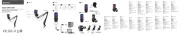
Bedienungsanleitung
Operating Instructions
KMS 140/150
Ollenhauerstr. 98
D-13403 Berlin
Tel.: +49-30 / 41 77 24-0
Fax: +49-30 / 41 77 24-50
Email: headoffice@neumann.com
Web: www.neumann.com

2
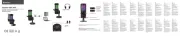
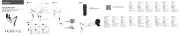
Inhaltsverzeichnis
1. Kurzbeschreibung
2. Die Kondensator-Solistenmikrophone
KMS 140 und KMS 150
3. Einige Zusatzinformationen zum Betrieb
4. Beschaltung des Mikrophonausgangs
5. Mikrophonkabel
6. Stromversorgung
7. Technische Daten
8. Frequenzgänge und Polardiagramme
9. Einige Hinweise zur Pflege von Mikrophonen
10. Zubehör
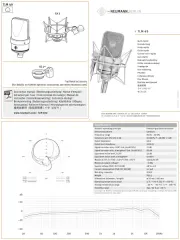
1. Kurzbeschreibung
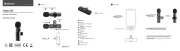
Die Kondensatormikrophone KMS 140 und KMS 150
sind Solistenmikrophone der Serie „fet 100®“ mit der
Richtcharakteristik Niere (KMS 140) bzw. Hyperniere
(KMS 150).
Sie zeichnen sich aus durch:
• einen eingebauten sehr wirksamen Schutz gegen
Pop- und Griffgeräusche,
• ein hoch aussteuerbares, transformatorloses Schal-
tungskonzept,
• niedriges Eigengeräusch und saubere, freie und ver-
färbungsfreie Klangübertragung. Die Mikrophone ha-
ben einen symmetrischen, übertragerlosen Aus-
gang.
Der 3-polige XLR-Steckverbinder hat folgende Bele-
gung:
Stift 1: 0 V/Masse
Stift 2: Modulation (+ Phase)
Stift 3: Modulation (– Phase)
Feldübertragungsfaktor ca. 12 mV/Pa = – 38 dBV re. 1 Pa.
Die Mikrophone werden mit 48 V, 2 mA phantom-
gespeist (IEC 1938). Die Einsprechrichtung ist axial.
Aufgrund des bei Solistenmikrophonen typischen kur-
zen Besprechungsabstandes ist der Baßfrequenzgang
entsprechend dem Naheffekt entzerrt (s. Frequenz-
gangkurven).
Table of Contents
1. A Short Description
2. The KMS 140 and KMS 150 Condenser Vocalist
Microphones
3. Additional Hints for Operating
4. Output Wiring
5. Microphone Cables
6. Power Supply
7. Technical Specification
8. Frequency Response and Polar Pattern
9. Some Remarks on Microphone Maintenance
10. Accessories
1. A Short Description
The KMS 140 and KMS 150 are condenser vocalist
microphones of the “fet 100®” Series with cardioid
(KMS 140) and hypercardioid (KMS 150) polar pattern.
Their most important features are
• a built-in very effective protection against pop- and
other explosive sounds,
• a high-loadability transformerless circuit,
• extraordinarily true sound transduction free of col-
oration. The microphones have a balanced, trans-
formerless output.
The 3-pin XLR connector has the following pin as-
signments:
Pin 1: 0 V/ground
Pin 2: Modulation (+ phase)
Pin 3: Modulation (– phase).
The output sensitivity is approx. 12 mV/Pa = – 38 dBV
re. 1 Pa. The microphones are phantom powered at
48 V, 2 mA (IEC 1938). The direction of maximum
sensitivity is axial.
Due to the close-talking typical for vocalist microphones
the low frequency response is equalized correspond-
ing to the proximity effect (see frequency response,
page 9).

4
3. Einige Zusatzinformationen zum
Betrieb
Der im Mikrophon eingebaute DC-DC-Wandler ver-
sorgt im Gegensatz zu bisherigen Schaltungskonzep-
ten auch den NF-Verstärker und nicht nur die Mikro-
phonkapsel. Da dieser Wandler Änderungen der
Versorgungsspannung ausregelt, versucht er dies auch,
wenn das Netz abgeschaltet wird. So bleibt die inter-
ne Spannung des Mikrophons noch ca. 2 Sekunden
erhalten, ehe sie mit einem hörbaren „Blubb“ zusam-
menbricht, gefolgt von einem kurzen Rauschen.
Vergleichbare Geräusche können auch beim Einschal-
ten der Stromversorgung auftreten und es dauert eini-
ge Sekunden, bis das Mikrophon übertragungsbereit ist.
Die meisten anderen Mikrophone haben keine vergleich-
bare „innere Spannungsversorgung“, so daß deren Ver-
stärker den Aufbau bzw. das Zusammenbrechen der
Polarisationsspannung nicht übertragen können.
Die Funktion „– 10 dB“ wird bei den Mikrophonen
KMS 140 und KMS 150 nicht durch Umschaltung der
Gegenkopplung im Verstärker erreicht, wie bei Mikro-
phonen der Serie „fet 80®“, sondern durch Verrin-
gern der Kapselvorspannung. Dieser Umladevorgang
dauert einige Sekunden, während derer das Mikro-
phon stummgeschaltet ist.
Das Zurückschalten zum vollen Übertragungspegel
kann, wie beim Einschalten des Mikrophons, mit ei-
nem kurzen Rauschen verbunden sein, bedingt durch
den oben beschriebenen Aufladevorgang.
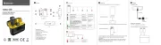
4. Beschaltung des
Mikrophonausgangs
Die Zuordnung des Mikrophonanschlusses entspricht
DIN 45 599, Kennzeichen „I“ bzw. IEC 268-12 (pin.
conn. 130-x-IEC 02):
Die Modulationsadern liegen an Stift 2 und 3, die Ab-
schirmung an Stift 1.
Bei einem Schalldruckanstieg vor der Mikrophonmem-
bran tritt an Stift 2 eine positive Spannung auf.
5. Mikrophonkabel
IC 3 mtIC 3 mtIC 3 mtIC 3 mtIC 3 mt ................................. sw .............................. Best.-Nr. 06543
10 m langes Mikrophonkabel ohne Stativgelenk (Switch-
craftkupplungen), es kann auch als Verlängerungskabel
verwendet werden. Mikrophonseitig mit schwarzmat-
3. Additional Hints for
Operating
The dc-dc converter installed in the microphone sup-
plies in contrast to other circuit conceptions also the
audio amplifier and not only the microphone capsule.
Since this converter compensates for variation of the
supply voltage it tries to do this also when the ac
main is switched off. Therefore the internal supply
voltage of the microphone is maintained for approxi-
mately 2 seconds before it collapses with an audible
“blubb” followed by a short noise.
Noises comparable to this can be recognized also
when switching the supply on and it takes some sec-
onds until the microphone is ready to operate.
Most of other microphones have no similar “internal
power supply” so that those amplifiers cannot trans-
mit the building up or breakdown of the polarizing
voltage.
The “–10 dB” function is not realized by changing
the negative feedback in the amplifier of the KMS 140
and KMS 150 microphones as is done with micro-
phones of the “fet 80®” series but by diminishing of
the capsule polarizing voltage. This procedure may last
some seconds during which the microphone is mute.
Returning to the full transmission level the microphone
can – as it is the case when switching it on – be
accompanied by a short noise caused by the above
mentioned increase of the polarizing voltage.
4. Microphone Output
Wiring
Microphone wired per IEC 268-12 (pin conn. 130-x-
IEC 02) or DIN 45 599 I, respectively:
Modulation is connected to pins 2 and 3, the shield
to pin 1.
A sudden sound pressure rise in front of the mem-
brane causes a positive voltage to appear at pin 2.
5. Microphone Cables
IC 3 mtIC 3 mtIC 3 mtIC 3 mtIC 3 mt ................................. blk .............................. Cat. No. 06543
10 m microphone cable without stand mount (Switch-
craft couplings) can also be used as extension cable.
With matt black connector at microphone end. Other
Product specificaties
| Merk: | Neumann |
| Categorie: | Microfoon |
| Model: | KM 76 |
Heb je hulp nodig?
Als je hulp nodig hebt met Neumann KM 76 stel dan hieronder een vraag en andere gebruikers zullen je antwoorden
Handleiding Microfoon Neumann

28 Februari 2025
28 Februari 2025

27 Februari 2025

2 December 2024

2 December 2024

2 December 2024

2 December 2024

16 November 2024

16 November 2024

16 November 2024
Handleiding Microfoon
- Hama
- Schertler
- Comica
- Day
- Lectrosonics
- NZXT
- QFX
- Audient
- Yamaha
- ESI
- Vaddio
- MKC
- Kalley
- MayBesta
- Musicmate
Nieuwste handleidingen voor Microfoon
15 September 2025
15 September 2025
15 September 2025
15 September 2025
15 September 2025

15 September 2025
15 September 2025
15 September 2025
13 September 2025
12 September 2025