NAV-TV NTV-KIT483 Handleiding
Bekijk gratis de handleiding van NAV-TV NTV-KIT483 (4 pagina’s), behorend tot de categorie Dashcam. Deze gids werd als nuttig beoordeeld door 10 mensen en kreeg gemiddeld 4.9 sterren uit 2 reviews. Heb je een vraag over NAV-TV NTV-KIT483 of wil je andere gebruikers van dit product iets vragen? Stel een vraag
Pagina 1/4
BHM
09/28/15
NTV-DOC 154
rB4
AgreementEnd user agrees to use this product in compliance with all State and Federal laws. NAV-TV Corp. would not be held liable for misuse of its product. :
If you do not agree, please discontinue use immediately and return product to place of purchase. This product is intended for off-road use and passenger
entertainment only.
1 | P a g e
3950 NW 120th Ave, Coral Springs, FL 33 TEL 561-955-9770 FAX 561-955-9760 065
www.nav-tv.cominf[email protected]m
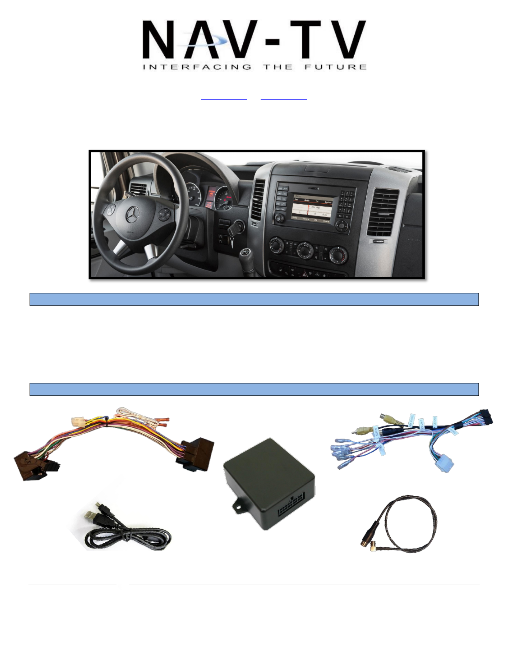
MB Sprinter-CAM
NTV-KIT477
Overview
The MB Sprinter-CAM allows the user to add an aermarket rear camera to the factory screen on the
Mercedes Sprinter. If desired, forced camera is an opon through a mounted toggle switch (not included).
ATTENTION: This module locks the VIN and can only be used on ONE vehicle at a me. to
Kit Contents
Plug & Play T Harness
NTV-HAR 081
SMB to RCA Adapter
NTV-CAB007
USB Cable (updates)
NTV-CAB009
MB Sprinter-CAM
Module
NTV-ASY171
CAN-XG Adapter
NTV-HAR058
Product specificaties
| Merk: | NAV-TV |
| Categorie: | Dashcam |
| Model: | NTV-KIT483 |
Heb je hulp nodig?
Als je hulp nodig hebt met NAV-TV NTV-KIT483 stel dan hieronder een vraag en andere gebruikers zullen je antwoorden
Handleiding Dashcam NAV-TV

12 November 2022
12 November 2022
12 November 2022
12 November 2022
12 November 2022
12 November 2022
12 November 2022
12 November 2022
12 November 2022
12 November 2022
Handleiding Dashcam
Nieuwste handleidingen voor Dashcam
9 Juli 2026
28 Mei 2026
27 Mei 2026
4 Mei 2026
29 April 2026
5 April 2026
31 Maart 2026
24 Maart 2026
6 Maart 2026
4 Maart 2026