Microchip HV257 Handleiding
Bekijk gratis de handleiding van Microchip HV257 (26 pagina’s), behorend tot de categorie Niet gecategoriseerd. Deze gids werd als nuttig beoordeeld door 52 mensen en kreeg gemiddeld 4.9 sterren uit 26.5 reviews. Heb je een vraag over Microchip HV257 of wil je andere gebruikers van dit product iets vragen? Stel een vraag
Pagina 1/26

2017 Microchip Technology Inc. DS20005827A-page 1
HV257
Features
• Thirty-two Independent High-voltage Amplifiers
• 300V Operating Voltage
• 295V Output Voltage
• 2.2V/µs Typical Output Slew Rate
• Adjustable Output Current Source Limit
• Adjustable Output Current Sink Limit
• Internal Closed-loop Gain of 72V/V
• 12 MΩ Feedback Impedance
• Layout Ideal for Die Applications
Applications
• Microelectromechanical Systems (MEMS) Driver
• Piezoelectric Transducer Driver
• Optical Crosspoint Switches
(Using MEMS Technology)
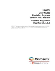
General Description
The HV257 is a 32-channel, high-voltage
sample-and-hold amplifier array integrated circuit. It
operates on a single high-voltage supply, up to 300V,
and two low-voltage supplies, VDD and VNN.
All 32 sample-and-hold circuits share a common
analog input, VSIG
. The individual sample-and-hold
circuits are selected by a five-to-32 logic decoder. The
sampled voltage on the holding capacitor is buffered by
a low-voltage amplifier and is magnified by a
high-voltage amplifier with a closed-loop gain of 72V/V.
The internal closed-loop gain is set for an input voltage
range of 0V to 4.096V. The input voltage can be up to
5V, but the output will saturate. The maximum output
voltage swing is 5V below the VPP high-voltage supply.
The outputs can drive capacitive loads of up to
3000 pF.
The maximum output source and sink current can be
adjusted by using two external resistors. An external
RSOURCE resistor controls the maximum sourcing
current, and an external RSINK resistor controls the
maximum sinking current. The current limit is
approximately 12.5V divided by the external resistor
value. The setting is common for all 32 outputs. A
low-voltage silicon junction diode is made available to
help monitor the die temperature.
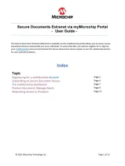
Package Type
100-lead MQFP
(Top view)
1
100
See Table 3-1 for pin information.
32-Channel High-Voltage Sample-and-Hold Amplifier Array

R
HVOUT0
AVNN
AVDD
S/H-0
5 to 32
Decoder
VSIG
A0
A1
A2
A3
EN
A4
R
S/H-1
HVOUT1
R
S/H-31
HVOUT31
VPP
AVDD
AVNN
AVNN
CH
-
+
-
+
Q0
Q1
Q31
HVOUT
Current
Sink
Limiting
To all HVOUT
amplifiers
RSOURCE
RSINK
DVDD
AVNN
DGND
AGND
VPP
AVDD
To internal VPP bus
To internal analog VDD bus
To internal analog VNN bus
To internal digital VDD bus
To internal digital VNN bus
DVDD
DVNN
AVDD
AVNN
CH
CH
BYP-VPP BYP-AVDD BYP-AVNN Anode Cathode
Bias Circuit
-
+
-
+
-
+
-
+
HVOUT
Current
Source
Limiting
To all HVOUT
amplifiers 71R
VPP
AVNN
71R
VPP
AVNN
71R
HV257
DS20005827A-page 2 2017 Microchip Technology Inc.
Functional Block Diagram

2017 Microchip Technology Inc. DS20005827A-page 3
HV257
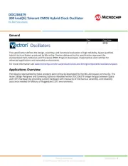
Typical Application Circuit
VSIG
A0
EN
A3
A2
A4
HVOUT0
HV257 High Voltage
Power Supply
Low Voltage
Power Supply
32
DGND AGND
HVOUT1
MEMS
Array
y
y
x
x
HVOUT2
HVOUT3
HVOUT30
HVOUT31
A1
VNN
Low Voltage
Channel
Select
Sample
and Hold
High
Voltage
OpAmp
Array
RSOURCE
RSINK
Micro
Processor
DAC
Product specificaties
| Merk: | Microchip |
| Categorie: | Niet gecategoriseerd |
| Model: | HV257 |
Heb je hulp nodig?
Als je hulp nodig hebt met Microchip HV257 stel dan hieronder een vraag en andere gebruikers zullen je antwoorden
Handleiding Niet gecategoriseerd Microchip
14 Mei 2025
6 Mei 2025

6 Mei 2025

6 Mei 2025

6 Mei 2025

6 Mei 2025

6 Mei 2025
6 Mei 2025
6 Mei 2025

6 Mei 2025
Handleiding Niet gecategoriseerd
- OutNowTech
- GermGuardian
- True
- Tovsto
- Honor
- Duro Pro
- AZZA
- SimGrade
- Konstant Lab
- Lascar Electronics
- Berkel
- ZAZU
- Arco
- Micsig
- Hanseatic
Nieuwste handleidingen voor Niet gecategoriseerd
17 September 2025

17 September 2025

17 September 2025

17 September 2025

17 September 2025

17 September 2025

17 September 2025

17 September 2025

17 September 2025

17 September 2025