Metra GMOS-05 Handleiding


Lees hieronder de 📖 handleiding in het Nederlandse voor Metra GMOS-05 (10 pagina's) in de categorie Niet gecategoriseerd. Deze handleiding was nuttig voor 16 personen en werd door 2 gebruikers gemiddeld met 4.5 sterren beoordeeld

Pagina 1/10
GMOS-05
I N S T A L L A T I O N I N S T R U C T I O N S
AxxessInterfaces.com © COPYRIGHT 2019 METRA ELECTRONICS CORPORATION REV. 7/3/19 INSTGMOS-05
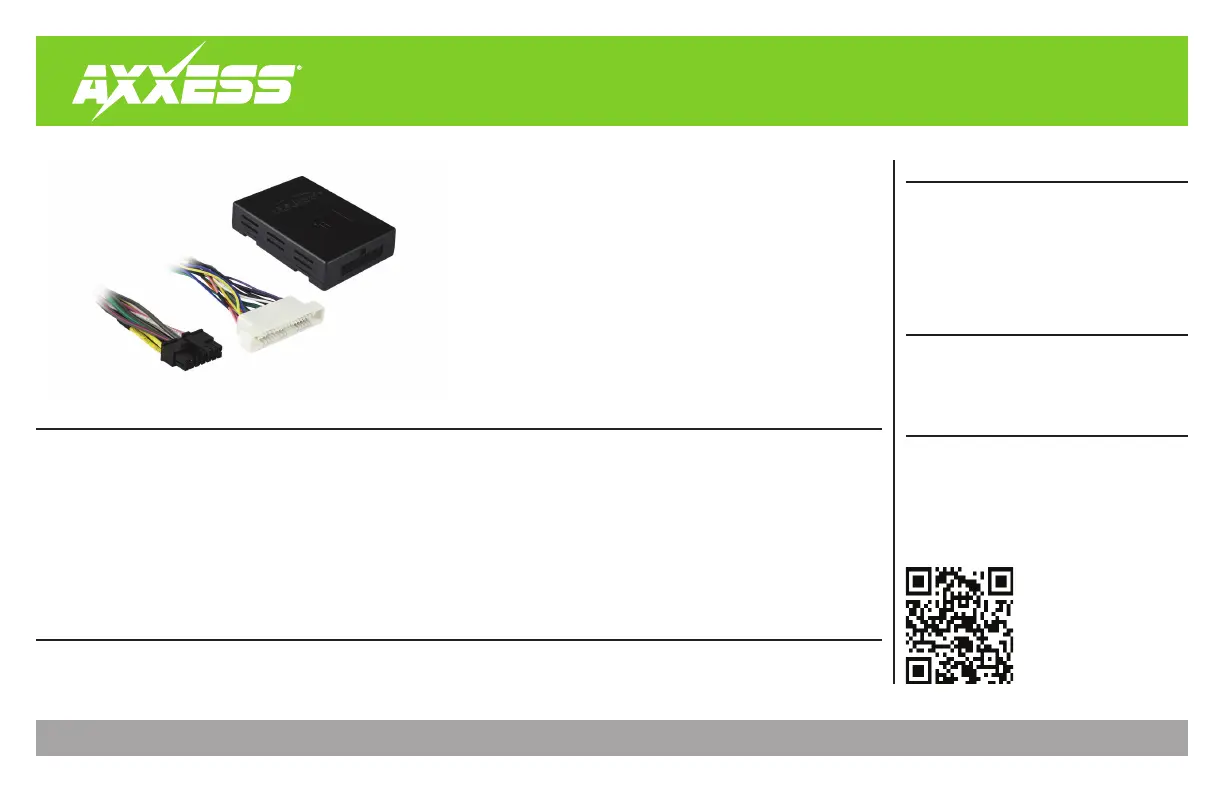
Product Info
INTERFACE FEATURES
INTERFACE COMPONENTS
TOOLS & INSTALLATION ACCESSORIES REQUIRED
• Crimping tool and connectors, or solder gun,
solder, and heat shrink • Tape • Wire cutter
• Zip ties • Multimeter • Small flat-blade screwdriver
TABLE OF CONTENTS
Connections ............................................................2
Installation .............................................................3
Programming .........................................................3
Adjustments ...........................................................3
GM Dock n’ Lock Data Interface
2000-2005
APPLICATIONS
• Provides accessory power (12-volt 10-amp)
• Retains R.A.P. (retained accessory power)
• Provides NAV outputs (parking brake, reverse, speed sense)
• Retains chimes to the factory speaker
• Adjustable chime level
• Retains OnStar / OE Bluetooth
• Adjustable OnStar level
Designed for non-amplified models, or when bypassing a factory amp *
• Retains balance and fade
• USB-CAB updatable (sold separately)
Buick
LeSabre 2000-2005
Oldsmobile
Aurora 2001-2003
Pontiac
Bonneville 2000-2005
• GMOS-05 interface • GMOS-05 harness
• 16-pin harness with stripped leads
* If the vehicle is amplified, either use the GMOS-09 interface, or bypass the amplifier. If bypassing the
amplifier, follow the “Axxess Interface Amp Bypass Schematic” online.
2
CONNECTIONS
From the 16-pin harness with stripped leads to the aftermarket radio:
Connect the wire to the accessory wire.Red
If the aftermarket radio has an illumination wire, connect the Orange/White wire to it.
If the aftermarket radio has a mute wire, connect the wire to it. If the mute wire is Brown
not connected, the radio will turn off when OnStar is activated.
Connect the wire to the right front positive speaker output.Gray
Connect the Gray/Black wire to the right front negative speaker output.
Connect the wire to the left front positive speaker output.White
Connect the wire to the left front negative speaker output.White/Black
The following (3) wires are only for multimedia/navigation radios that require these wires.
Connect the wire to the VSS/speed sense wire.Blue/Pink
Connect the wire to the reverse wire.Green/Purple
Connect the wire to the parking brake wire. Light Green
From the GMOS-05 harness to the aftermarket radio:
Connect the wire to the ground wire.Black
Connect the Yellow wire to the battery wire.
Connect the wire to the power antenna wire.Blue
Connect the wire to the left rear positive speaker output.Green
Connect the wire to the left rear negative speaker output.Green/Black
Connect the wire to the right rear positive speaker output.Purple
Connect the wire to the right rear negative speaker output.Purple/Black
The Black/Yellow wire is used for OnStar level adjustment for models that do not come
equipped with steering wheel controls. See the OnStar level Adjustment section for further
instructions.
Tape off and disregard the following (3) wires, they will not be used in this application:
Orange Blue/White (qty. 2) ,
3
REV. 7/3/2019 INSTGMOS-05
With the key in the off position:
Connect the 16-pin harness with stripped leads, and the GMOS-05 harness, into the interface.
Connect the GMOS-05 harness to the wiring harness in the vehicle.
Attention! If the interface loses power for any reason, the following steps will need to be performed
again. Also, if installing an ASWC-1 connect it after you initialize and test the interface/radio, with the
key in the off position.
Turn the key (or push-to-start button) to the ignition position and wait until the radio comes on.
If the radio does not come on within 60 seconds, turn the key to the off position, Note:
disconnect the interface, check all connections, reconnect the interface, and then try again.
Turn the key to the off position, and then to the accessory position. Test all functions of the
installation for proper operation, before reassembling the dash.
Chime level adjustment:
Turn the vehicle off but leave the keys in the ignition. Open the driver’s door and leave it
open; chimes will be heard.
Wait 10 seconds, and then with a small flat-blade screwdriver, adjust the potentiometer
clockwise to raise the chime level; counterclockwise to lower the chime level.
The potentiometer is located on the side of the interface where the 16-pin harness Note:
with stripped leads is connected to.
When the chime is at the desired level, remove the keys from the ignition. This will lock
the chime level in at its current level.
OnStar level adjustment:
Press the OnStar button to activate it.
While OnStar is speaking, press the VOLUME UP or VOLUME DOWN buttons on the steering
wheel to raise or lower the OnStar level.
If the vehicle does not come equipped with steering wheel controls, locate the Black/
Yellow wire on the GMOS-05 harness.
While OnStar is speaking, tap the Black/Yellow wire to ground. Once the OnStar level is
set, it will stay at that level until the Black/Yellow wire is tapped to ground again.
INSTALLATION
PROGRAMMING
ADJUSTMENTS


Product specificaties

Merk: Metra
Categorie: Niet gecategoriseerd
Model: GMOS-05

Heb je hulp nodig?

Als je hulp nodig hebt met Metra GMOS-05 stel dan hieronder een vraag en andere gebruikers zullen je antwoorden


Handleiding Niet gecategoriseerd Metra

Handleiding Niet gecategoriseerd

Nieuwste handleidingen voor Niet gecategoriseerd