Metra 99-7510 Handleiding
Metra Niet gecategoriseerd 99-7510
Bekijk gratis de handleiding van Metra 99-7510 (8 pagina’s), behorend tot de categorie Niet gecategoriseerd. Deze gids werd als nuttig beoordeeld door 89 mensen en kreeg gemiddeld 5.0 sterren uit 4 reviews. Heb je een vraag over Metra 99-7510 of wil je andere gebruikers van dit product iets vragen? Stel een vraag
Pagina 1/8
METRA - The World’s best kits
®
metraonline.com
REV. 12/21/2016 INST99-7510
Installation instructions for part 99-7510
®
CAUTION!
All accessories, switches, climate controls panels, and
especially air bag indicator lights must be connected before cycling
the ignition. Also, do not remove the factory radio with the key in the
on position, or while the vehicle is running.
© COPYRIGHT 2016 METRA ELECTRONICS CORPORATION
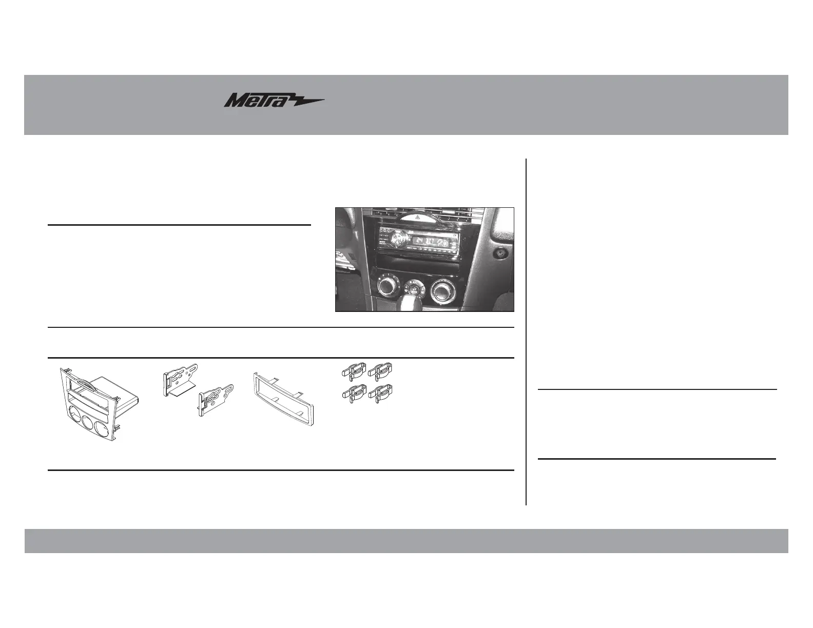
• DIN radio provision with pocket
• ISO DIN radio provision with pocket
• Two finishes available:
99-7510 = Black
99-7510HG = Gloss Black
• A) Radio/climate control housing • B) ISO DIN brackets • C) ISO DIN trim plate • D) (4) Plastic panel clips
• E) Axxess Interface and wiring harness (not shown)
20;-,(;<9,:
20;*64765,5;:
>0905.(5;,55(*655,*;065:
Wiring Harness: • Axxess interface and wiring harness included
Antenna Adapter: • Not required
• Panel removal tool • Phillips screwdriver
• 10mm socket wrench • Cutting tool
;663:9,8<09,+
Mazda RX-8 2004-2008
99-7510, 99-7510HG
A
BC
D
Dash Disassembly .................................................2
Kit Preparation ....................................................3-4
Kit Assembly
–DIN radio provision with pocket ............................4
–ISO DIN radio provision with pocket ......................5
Axxess Interface Installation .............................5-7
Display Customization ........................................7-8
Table of Contents
Product specificaties
| Merk: | Metra |
| Categorie: | Niet gecategoriseerd |
| Model: | 99-7510 |
Heb je hulp nodig?
Als je hulp nodig hebt met Metra 99-7510 stel dan hieronder een vraag en andere gebruikers zullen je antwoorden
Handleiding Niet gecategoriseerd Metra

6 November 2025
5 November 2025
5 November 2025
4 November 2025
4 November 2025
4 November 2025
3 November 2025
31 Oktober 2025
30 Oktober 2025
28 Oktober 2025
Handleiding Niet gecategoriseerd
Nieuwste handleidingen voor Niet gecategoriseerd
8 Juni 2026
8 Juni 2026
8 Juni 2026
8 Juni 2026
8 Juni 2026
8 Juni 2026
8 Juni 2026
8 Juni 2026
7 Juni 2026
7 Juni 2026