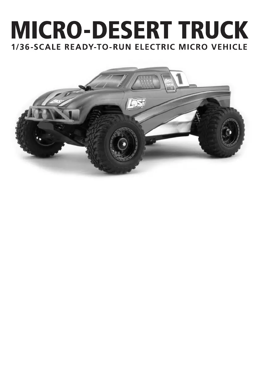
Losi 1/36 Micro-Desert Truck RTR Handleiding

Losi Radiografisch bestuurbaar speelgoed 1/36 Micro-Desert Truck RTR

Lees hieronder de 📖 handleiding in het Nederlandse voor Losi 1/36 Micro-Desert Truck RTR (8 pagina's) in de categorie Radiografisch bestuurbaar speelgoed. Deze handleiding was nuttig voor 13 personen en werd door 2 gebruikers gemiddeld met 4.5 sterren beoordeeld

Pagina 1/8
Operations Guide
Warning
Although the best materials and components are used, and due to the size of this model,
using anything other than genuine Losi replacement and performance parts specically
designed for the Losi Micro-DT could cause damage.
Customer Service Information:
Horizon Hobby Customer Service
4105 Fieldstone Rd.
Champaign, IL, 61822
1-877-504-0233
www.horizonhobby.com
email: productsupport@horizonhobby.com
Introduction
Thank you for choosing the Micro-DT from Losi. This guide contains the basic instructions for
operating your new Micro-DT. While the Micro-DT is great for rst-time RC drivers, it does require
some mechanical experience and/or parental supervision for drivers under 12 years of age. It is
critical that you read all of the instructions and all accompanying printed material in order to oper-
ate your model correctly and avoid unnecessary damage. Please take a moment to look them
over before running your model.
DO NOT RUN YOUR MICRO-DT ON PLUSH CARPET, GRASS OR SAND.
2007 Losi, A Division of Horizon Hobby Inc.
Safety Precautions
This is a sophisticated radio controlled model that must be operated with caution and common
sense. Failure to operate your Micro-DT in a safe and responsible manner could result in dam-
age to the model and property. The Micro-DT is not intended for use by children without direct
adult supervision. Losi and Horizon Hobby shall not be liable for any loss or damages, whether
direct, indirect, special, incidental, or consequential, arising from the use, misuse, or abuse of
this product or any product required to operate it.
This model is controlled by a radio signal that is subject to interference from many sources
outside your control. This interference can cause momentary loss of control so it is advisable
to always keep a safety margin in all directions to avoid collisions.
Always operate your model in an open area away from cars, trafc and people.
Never run out into the street for any reason.
Never run your Micro-DT with low transmitter batteries.
Carefully follow the directions and warnings for this and any optional support equipment that
you use.
Keep all chemicals, small parts and anything electrical out of the reach of children.
Tools and Items You Will Find Handy
Soft bristle brush for cleaning
#00 Phillips screwdriver
4.5mm nut driver
Small at blade screwdriver
Note: Use only Losi or other high-quality tools. Use of inexpensive tools can cause damage to
the small screws and parts used on this type of model.
The Transmitter
Steering Wheel: Controls direction (left/right) of the model.
Throttle Trigger: Controls speed and direction (forward/reverse) of the model.
Antenna: Transmits signal to the model.
On/Off Switch: Turns the power on/off for the transmitter.
Indicator Lights: Green (right) light indicates adequate battery power.
Red (left) indicates signal strength.
ST. Trim: Adjusts the “hands off” direction of the model.
TH. Trim: Adjusts the motor speed to stop at neutral.
Steering Rate: Adjusts amount front wheels move
when the steering wheel is turned left and right.
ST. REV: Reverses the function of the steering
when the wheel is turned left or right.
TH. REV: Reverses the function of the speed control
when pulled back or pushed forward.
Bottom Cover: Covers and holds the batteries that
power the transmitter.
Transmitter Crystal: Determines frequency/channel
you transmit on. The receiver must have a matching
frequency/channel to operate.
Transmitter
Crystal
Throttle
Trigger
2
TH. Rev ST. Rev
Antenna
Indicator
Lights
On/Off
Switch
Steering
Rate
ST. Trim
TH. Trim
Steering
WheelThrottle
Trigger
Battery Door
The Receiver/Speed Control
Receiver/Electronic Speed Control: Receives
the signal from the transmitter to control the
model’s power and direction of the motor.
Receiver Crystal: Determines which channel it
will receive.
On/Off Switch: Controls power to the receiver.
Antenna Wire: Receives the signal from the
transmitter.
Power Plug: Connects battery pack to the
receiver/speed control.
Steering Servo: Controls steering movement.
Steering Servo Plug: Receiver connection and
power supply.
Motor Plugs: Power connection from the speed
control.
Changing Frequencies/Channels
The Micro radio operates on 27MHz AM and has 6 different frequencies/channels available.
Simply put, a frequency is like a TV channel. The transmitter you hold in your hand is like the TV
station and the model with the matching crystal is like your TV tuned exclusively to the channel
of the station. The Micro radio is equipped with changeable crystals that allow you to change
the frequency/channel you operate on. This is especially useful when you want to run a group of
Losi Micro’s at the same time. When changing crystals/channels, you must always replace the
crystals as a set with one going in both the transmitter and the receiver in the truck. Each of the
6 different channels are numbered and color-coded. Each set includes a unique crystal for the
receiver marked (Rx) and one from the transmitter marked (Tx). The crystals are changed by
gently pulling them out, later lining up the two pins of each crystal with its socket, then carefully
pushing the new crystals into place. force them as damage can occur. DO NOT If they do not
slide into the socket easily check for bent or misaligned pins.
Channel 1 Brown 26.995MHz (LOSB1094)
Channel 2 Red 27.045MHz (LOSB1095)
Channel 3 Orange 27.095MHz (LOSB1096)
Channel 4 Yellow 27.145MHz (LOSB1097)
Channel 5 Green 27.195MHz (LOSB1098)
Channel 6 Blue 27.255MHz (LOSB1099)
Making Adjustments
The following are simple adjustments and easily maintained settings that will assure proper
operation and performance. The Losi Micro-DT comes from the factory with optimum settings,
we suggest rst-time RC drivers leave these as they are and simply maintain them as necessary.
Only after gaining experience should new drivers try experimenting with different settings.
Slipper Adjustments
The Losi Micro-DT is equipped with a slipper device that offers
both traction control and protection for the transmission. The
slipper is primarily used to help absorb sudden impacts on
the drivetrain due to landing big jumps or when using more
powerful after-market motors and/or battery packs. Addition-
ally, it can be used to smooth out the ow of power to the rear
wheels and limit wheel spin when running on extremely slick
surfaces. Adjustments are made using a 4.5mm nut driver and
adjusting the slipper nut clockwise (to the right) to reduce the
slip or counterclockwise (to the left) to increase the slip.
3
Motor PlugReceiver CrystalPower PlugServo Plug
Steering
Servo
On/Off Switch
Crystal
Socket
Increase
Slip
Decrease
Slip
Bottom
View


Product specificaties

Merk: Losi
Categorie: Radiografisch bestuurbaar speelgoed
Model: 1/36 Micro-Desert Truck RTR
Gewicht: 112 g
Breedte: 89 mm
Capaciteit van de accu/batterij: 150 mAh
Frequentieband: 0.027 GHz
Batterijtechnologie: Nikkel-Metaalhydride (NiMH)

Heb je hulp nodig?

Als je hulp nodig hebt met Losi 1/36 Micro-Desert Truck RTR stel dan hieronder een vraag en andere gebruikers zullen je antwoorden


Handleiding Radiografisch bestuurbaar speelgoed Losi

Handleiding Radiografisch bestuurbaar speelgoed

Nieuwste handleidingen voor Radiografisch bestuurbaar speelgoed