Joy-it DSO-138 Handleiding
Joy-it Niet gecategoriseerd DSO-138
Bekijk gratis de handleiding van Joy-it DSO-138 (4 pagina’s), behorend tot de categorie Niet gecategoriseerd. Deze gids werd als nuttig beoordeeld door 13 mensen en kreeg gemiddeld 4.7 sterren uit 3 reviews. Heb je een vraag over Joy-it DSO-138 of wil je andere gebruikers van dit product iets vragen? Stel een vraag
Pagina 1/4
Iron(20W)
1
Solderwire
Multimeter
Screwdriver
UserManual
Rev.05
DSO138 OscilloscopeDIYKit
2
3
4
Flushcutter
5
Toolsyouneed
Tweezers
6
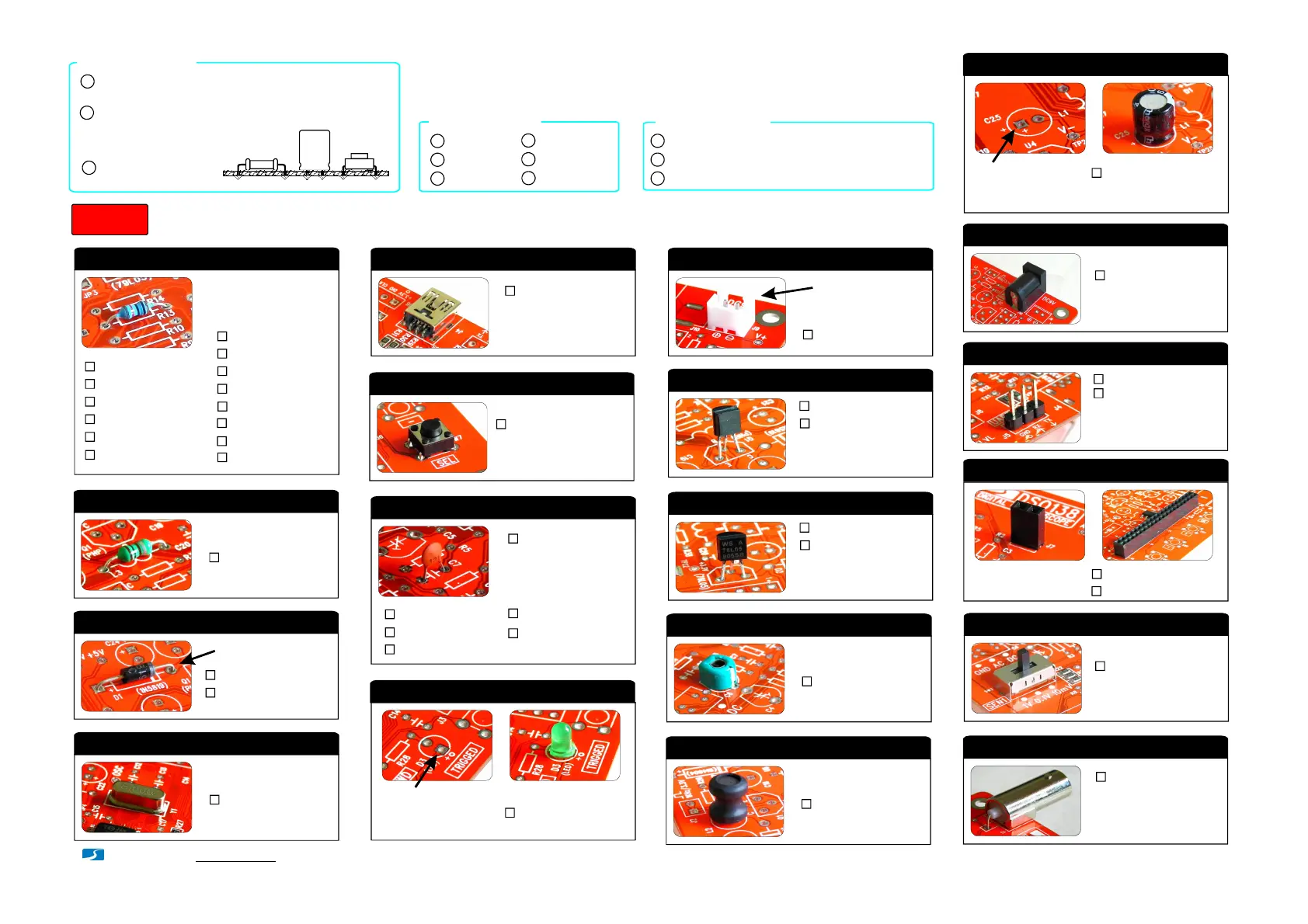
AssemblyMainBoardandLCD board(followthe order asnumbered)
Step 1
- www.jyetech.com -
JYETechLtd.
1.Resistors
Alwaysmeter resistor
valuesbefore soldering
Note:
R1,R14,R16
100KΩ
R2
1.8MΩ
:
:
R3
200KΩ:
R4
2MΩ:
R5
20KΩ:
R6
300Ω:
R7,R36
180Ω
R8,R12,R13
120Ω
:
:
R9,R15,R26
1KΩ
:
R10
3KΩ
:
R38
1.5KΩ
:
R28,R40
470Ω
:
R37,R39
10KΩ
:
L1,L3,L4
100Hμ
2.HF-Chokes
:
D1
1N5819
3.Diodes
:
D2
1N4004
:
(or1N4007)
Y1
8MHz
4.Crystal
:
J4USBmini -B
5.USB Socket *
:
6 X 6 X5mm
6. TactSwitches
:
SW4, SW5,
SW6, SW7,
SW8
7.Ceramic Capacitors
0.1F
μ
:
330pF:
3pF:
C1,C9,
C10,C11,
C14,C15,
C16,C17,
C18,C20,
C23
1pF:
C7,C8
120pF
:
C12,C13
22pF
:
C2
C3
C5
D3
8.LED
:
φ3mm,green
Solderpositivepole
(thelongerlead)to
thesquarepad
J9
2Pin
9.Pin header(forpower)
:
Facetheopening
outward
8550
10.Transistors
:
Q1
9014
:
Q2
Cathode
79L05
11.Regulators
:
U4
78L05
:
U5
C4, C6
5-30pF
12.Capacitortrimmers
:
L2
1mH/0.5A
13.Power inductor
:
14. Electrolyticcapacitors
:
100μ/16VF
Solderpositivepole
(thelongerlead)to
thesquarepad
C19,C21,
C22,C24,
C25,C26
DC005
15. Powerconnector
:
J10
16. Pin-header(male) *
1 X 3pin
:
J5
1 X 4pin
:
J6
17.Pin-header(female)
:
1X2pin
J7,J8
:
2X20pin
J3
SW1, SW2,
SW3
2P3T
18.Slide switches
:
J1
BNC
19. BNC connector
:
Putleads throughmountingholesfromthe side with
partoutline.Ensue component evenly touch PCB.
1
Solderleads atthe otherside.Solder shouldfully
fillandcoversolderingpads.
Avoidbridgesbetween
neighberingpads.
Cut unusedleads
flushwithcutter.
2
3
SolderingHints
Checkpart values&quantitiesagainstpartlist
1
Alwaysmeterresistorvaluesbeforesoldering
Understandall partpolaritiesandorientations
2
3
Beforeyou start
Page 1
Packagesaresimilar.
Donot mixup!
Attention!
Packagesaresimilar.
Donot mixup!
Attention!
The thicker pins need
toheat uplonger to get
good solderingresult.
Note:
R11
150Ω
:
Thesepin-headersare
optional.
Note:
Applicablemodels:13803K, 13804K
InstallallSMDpartsbeforeproceeding
toStep1ifyoupurchasedkit13804K.
Important!!!
This connectoris
optional.
Note:
Applicablefirmware: 113-13801-060orlater
Product specificaties
| Merk: | Joy-it |
| Categorie: | Niet gecategoriseerd |
| Model: | DSO-138 |
| Gewicht: | 70 g |
| Breedte: | 117 mm |
| Diepte: | 76 mm |
| Hoogte: | 15 mm |
| Soort: | Draagbaar |
| Aantal kanalen: | - kanalen |
| Bandbreedte: | 0.2 MHz |
| Type product: | Digitale geheugen-oscilloscoop (DSO) |
| Type beeldscherm: | LCD |
| Synchronisatie ingangsimpedantie: | 1000000 Ohm |
| Bemonsteringsfrequentie: | 1 MS/s |
| Verticale resolutie: | 12 Bit |
| Minimale tijdbasisinstelling (per divisie): | 10000 ns |
| Minimale verticale gevoeligheid (per divisie): | 10 mV |
| Maximale resolutie (tellingen): | 1024 |
Heb je hulp nodig?
Als je hulp nodig hebt met Joy-it DSO-138 stel dan hieronder een vraag en andere gebruikers zullen je antwoorden
Handleiding Niet gecategoriseerd Joy-it

13 Mei 2026
12 Mei 2026
11 Mei 2026
2 Maart 2026
24 November 2025
30 September 2025
29 September 2025
4 Augustus 2025
4 Augustus 2025
4 Augustus 2025
Handleiding Niet gecategoriseerd
Nieuwste handleidingen voor Niet gecategoriseerd
8 Juni 2026
8 Juni 2026
8 Juni 2026
7 Juni 2026
7 Juni 2026
7 Juni 2026
7 Juni 2026
7 Juni 2026
6 Juni 2026
6 Juni 2026