JobSite IR-E2 Handleiding
JobSite Niet gecategoriseerd IR-E2
Bekijk gratis de handleiding van JobSite IR-E2 (2 pagina’s), behorend tot de categorie Niet gecategoriseerd. Deze gids werd als nuttig beoordeeld door 28 mensen en kreeg gemiddeld 4.7 sterren uit 9 reviews. Heb je een vraag over JobSite IR-E2 of wil je andere gebruikers van dit product iets vragen? Stel een vraag
Pagina 1/2
IR Blocking
Cover
INCREASING THE WIRE LENGTH
If the connecting wire is too short to reach the IR
Connecting Blocks, an additional length of wire
may be spliced in to extend it. Cut the emitter wire
approximately six inches from the plug end, strip off
1/4", and connect your additional wiring between
the ends of the original emitter wire. For distances
between 10 and 20 feet upgrade the original wire to
an 18 gauge 2-conductor wire. For distances of up
to 200 feet a 16 gauge two-conductor wire should
be used.
Be sure to observe proper polarity when extending
the emitter wire.
The wire lead marked with a gray stripe is positive
(+); the unmarked lead is negative (-).
USING THE IR
BLOCKING COVER
To prevent A/V components from receiving IR
commands from sources other than the IR-E1 and
IR-E2, the IR Blocking Cover should be used. The IR
Blocking Cover is designed to cover both the IR-E1
and IR-E2 and the IR Receiver window of the
component. The IR Blocking Cover serves two
functions:
1. It ensures that a component receives IR signals
solely from the IR-E1 and IR-E2.
2. It prevents the IR output of the IR-E1 and IR-E2
from radiating to other components or IR
receivers.
FEATURES
nInfrared pass through housing
nMiniature size and shape
Installation friendly design:
n10' of cable with 3.5mm plug
nReliable adhesive backing
nIncludes IR blocking cover
PACKAGE CONTENTS: IR-E1
nIR-E1 Emitter x 1
n10 Feet of Connecting Wire x 1
nIR Blocking Cover x 1
nExtra Emitter Adhesive strips x 2
PACKAGE CONTENTS: IR-E2
nIR-E2 Emitter x 1
n10 Feet of connecting wire x 1
nIR Blocking Covers x 2
nExtra emitter adhesive strips x 4
145
Infrared
Transparent
Housing
10feetof
2-conductor
24gauge
connecting
wire
3.5mmmo
no mini-
plug
Self-adhesive tape
236
MOUNTING THE
IR BLOCKING COVER
Make sure the mounting surface is clean before
installing the blocking cover. You may improve
the appearance by trimming the cover with
scissors to exactly cover the remote receiver
window. Mount the blocking cover (using the
self-adhesive tape) so that the IR-E1 and IR-E2
and the IR remote receiver window of the
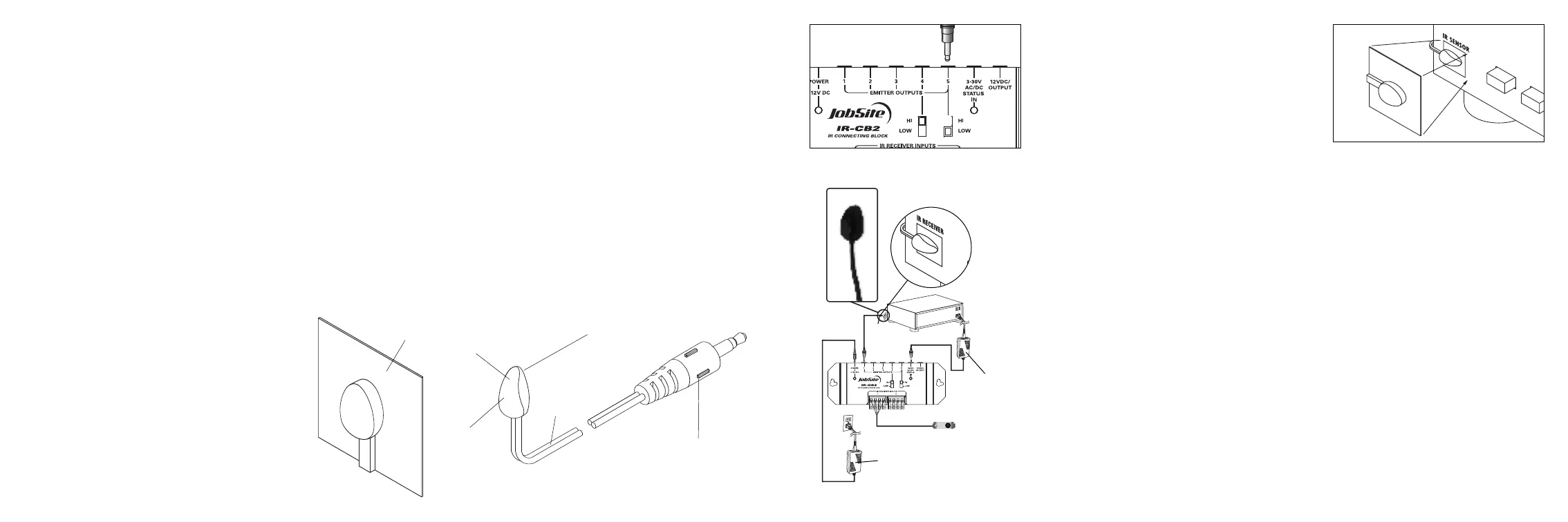
component are completely covered. See figure 4.
TROUBLESHOOTING
Testing the Remote Control
Test to see that the hand-held remote control
operates the component when you point it at the
front panel (check the batteries if it does not).
IR Connecting Blocks Power Supply
Check that the red power light on the IR
Connecting Blocks is lit (the in-line power supply
should be plugged into an active AC wall outlet
and supplying 12V DC).
Over Please
Figure 1
PREPARING FOR
INSTALLATION
The IR-E1 and IR-E2 are typically mounted to the
infrared remote receiver windows of audio/video
components, using the attached self-adhesive
tape. The emitter directs its infrared output
toward the component, not out into the room. If
the component has a tray or door that opens, you
may have to route the emitter wire from the top
or the side of the component. Make sure the
mounting surface is cleaned and degreased
before installation.
PRODUCT OVERVIEW
Infrared
LED
Figure 2Connecting the emitter to the main
system unit’s emitter low outputs.
Figure 4Mounting theIR BlockingCover.
12V DC
Power Supply
(Not Supplied)
plugged into the
Switched Outlet
12V DC Power Supply
Plugged into an
Unswitched AC Outlet
Powers the System
IR-CB2
JobSite
IR-E1/E2
Emitter
IR-SMR
Stereo Receiver
IR-E1/E2
Figure 3
INSTALLATION
1. Locate the IR remote receiver window of each
component to control. The receiver is usually
located behind its own plastic window, on the
front of the component.
2. Make sure the mounting surface is clean.
3. Attach the IR-E1/E2 directly over the IR remote
receiver windows of the components using its
self-adhesive tape.
4. Route the connecting two-conductor wire to
the IR Connecting Block and plug it into an
Emitter output.
5. Coil any excess wire and tie it in place.
6. On IR Connecting Blocks with selectable
Emitter outputs, make certain the HI-LOW
SWITCH is placed in the LOW position. See
figure 2 and 3.
Product specificaties
| Merk: | JobSite |
| Categorie: | Niet gecategoriseerd |
| Model: | IR-E2 |
Heb je hulp nodig?
Als je hulp nodig hebt met JobSite IR-E2 stel dan hieronder een vraag en andere gebruikers zullen je antwoorden
Handleiding Niet gecategoriseerd JobSite

13 Februari 2024
13 Februari 2024
13 Februari 2024
13 Februari 2024
13 Februari 2024
13 Februari 2024
13 Februari 2024
13 Februari 2024
13 Februari 2024
13 Februari 2024
Handleiding Niet gecategoriseerd
Nieuwste handleidingen voor Niet gecategoriseerd
25 Augustus 2026
25 Augustus 2026
25 Augustus 2026
25 Augustus 2026
25 Augustus 2026
25 Augustus 2026
25 Augustus 2026
25 Augustus 2026
25 Augustus 2026
25 Augustus 2026