Janitza RCM 201-ROGO Handleiding
Janitza Meetapparatuur RCM 201-ROGO
Bekijk gratis de handleiding van Janitza RCM 201-ROGO (2 pagina’s), behorend tot de categorie Meetapparatuur. Deze gids werd als nuttig beoordeeld door 17 mensen en kreeg gemiddeld 4.6 sterren uit 7 reviews. Heb je een vraag over Janitza RCM 201-ROGO of wil je andere gebruikers van dit product iets vragen? Stel een vraag
Pagina 1/2
Eigenschaften
• Janitza
®
Messumformer RogoTrans für Janitza
®
Rogowski-Stromwandler
• normiertes Ausgangssignal 0 ... 1 A
• universelle Anwendungen zur Messung von Wechselströmen
• Messbereiche 250 ... 4000 A
• Spannungsversorgung: 24 V DC
• Kompakte Bauform im Kunststoffgehäuse
• Montage auf DIN-Schiene möglich
Kurzbeschreibung
• Dem Janitza
®
Messumformer RogoTrans wird das Ausgangssignal eines Janitza
®
Rogowski-Stromwandlers zugeführt.
• Der Janitza
®
Messumformer RogoTrans gibt am Ausgang einen AC-Strom von
maximal 1 A aus.
• Mit dem Janitza
®
Messumformer RogoTrans können Sie zwischen fünf Strom-
messbereichen von 250 A AC bis 4.000 A AC wählen.
Weitere Informationen zum Janitza® Rogowski-Stromwandlers entnehmen Sie bitte
der separaten Betriebsanleitung zum Stromwandler.
• Nur elektrotechnisch qualifiziertes Fachpersonal darf das Gerät installieren, in Be-
trieb nehmen, warten und bedienen.
• Halten Sie bei allen Arbeiten am Gerät die nationalen Sicherheits- und Unfallver-
hütungsvorschriften ein.
• Wenn Sie die Sicherheitsvorschriften nicht beachten, können Tod, schwere Kör-
perverletzung oder hoher Sachschaden die Folge sein.
• Halten Sie die für das Errichten und Betreiben geltenden Bestimmungen und Si-
cherheitsvorschriften (auch nationale Sicherheitsvorschriften) sowie die allgemei-
nen Regeln der Technik ein.
• Befolgen Sie die beschriebenen Installationsanweisungen!
• Schalten Sie die Anlage vor Beginn der Arbeiten spannungsfrei. Spannungsfrei-
heit prüfen!
• Schalten Sie das Gerät vor Beginn der Arbeiten spannungsfrei. Spannungsfreiheit
prüfen!
• Die sicherheitstechnischen Daten sind diesem Dokument und den Zertifikaten
(EG-Baumusterprüfbescheinigung, ggf.weitere Approbationen) zu entnehmen.
• Überschreiten Sie nicht die in der Betriebsanleitung und auf dem Typenschild
angegebenen Grenzwerte.
• Betreiben Sie Betriebsmittel und Stromwandlerkreise nicht offen.
• Das Öffnen oder Verändern des Gerätes ist unzulässig. Reparieren Sie das
Gerät nicht selbst , sondern ersetzen Sie es durch ein gleichwertiges Gerät.
• Reparaturen dürfen nur vom Hersteller vorgenommen werden. Der Hersteller
haftet nicht für Schäden aus Zuwiderhandlung.
• Bauen Sie das Gerät zum Schutz gegen mechanische oder elektrische Beschä-
digungen in ein entsprechendes Gehäuse mit einer geeigneten Schutzart nach
IEC 60529 ein.
• Der einwandfreie und sichere Betrieb des Gerätes setzt sachgemäßen Transport,
sachgemäße Lagerung, Aufstellung und Montage, sowie Bedienung und Instand-
haltung voraus.
• Benutzen Sie nur Zubehör, das den Festlegungen des Herstellers des Gerätes
entspricht (z. B. Kombination Janitza
®
Messumformer RogoTrans und Janitza
®
Stromwandler).
• Bewahren Sie die Produktdokumentation auf.
Artikelnummer 15.03.613
Abmessungen 22,5 x 100 x 110 mm (B x H x T)
Gewichtca. 0,2 kg
Stromversorgung24 V DC (18…36 V) / 1 A
Stromaufnahme< 300 mA (bei 1 A Ausgangsstrom)
< 80 mA (ohne Ausgangsstrom)
EingangJanitza
®
Rogowski-Stromwandler
max. 90mV (4000 A Bereich)
Strom-Messbereiche1 ... 4000 A
1 ... 2000 A
1 ... 1000 A
1 ... 500 A
1 ... 250 A
Messbereichseinstellung (Taster)
LED (gelb)
Verschleißfreie Messbereichswahl über
Mikrocontroller und PGA
Betriebs- und Messbereichsanzeigeüber 6 LED (grün)
Phasenwinkel< 1°
Linearitätsfehler bei 50 Hz
Messfehler bei 50 Hz
< 0,2 % in allen Messbereichen
< 0,2 % in allen Messbereichen
Eingangsimpedanz10 kΩ in allen Messbereichen
Signalausgang0 ... 1A
Messbereichsüberschreitung110%
Bürde0 ... 1,5 Ω
Linearitätsfehler Bürde 0...1,5Ohm< 0,02 %
Alarmausgang24 V DC / 200 mA (potentialfreier Opto-
ausgang, bei Fehler öffnend)
Alarmmeldungen
(über LED rot)
Überlast (Bereichsüberschreitung)
Bürde zu groß (Ausgangskreis)
Unterspannung (24 V)
Alarmverzögerung60 Sekunden
SchutzartIP30
Umgebungstemperatur- 20 °C ... 70 °C
EinbaulageSenkrecht; bei Einsatz mehrerer Geräte
nebeneinander ist zwischen den Geräten
ein Mindestabstand von 5 mm einzuhalten
(Wärmeentwicklung)
Lagertemperatur- 25 °C ... 85 °C
Warnung!
Lesen Sie die Bedienungsanleitung sorgfältig durch!
CE - Konformität, dieses Produkt erfüllt die Bestimmungen
der Niederspannungsrichtlinie 2014/35/EU
Die „Betriebsanleitung“ stellt kein vollständiges Verzeichnis aller für einen Betrieb des
Geräts erforderlichen Sicherheitsmaßnahmen dar.
Besondere Betriebsbedingungen können weitere Maßnahmen erfordern. Die „Be-
triebsanleitung“ enthält Hinweise, die Sie zu Ihrer persönlichen Sicherheit und zur
Vermeidung von Sachschäden beachten müssen.
Verwendete Symbole:
c
Dieses Symbol als Zusatz zu den Sicherheitshinweisen deutet
auf eine elektrische Gefahr hin.
m
Dieses Symbol als Zusatz zu den Sicherheitshinweisen deutet
auf eine potenzielle Gefahr hin.
C
Dieses Symbol mit dem Wort
HINWEIS! beschreibt:
• Verfahren, die keine Verletzungsgefahren bergen.
• Wichtige Informationen, Verfahren oder Handhabungen.
• Schließen Sie am Eingang den auf den Janitza
®
Messumformer abgestimmten
Janitza
®
Rogowski-Stromwandler an!
• Der Janitza
®
Rogowski-Stromwandler sowie dessen Zuleitung dürfen keine Be-
schädigung der Isolation aufweisen.
• Das Ausgangssignal (1 A) darf nur mit potentialgetrennten 1 A Stromwandlerein-
gängen verbunden werden.
• Eine Verbindung des Eingangs- oder Ausgangssignals mit einer externen Span-
nung ist nicht zulässig und kann zur Zerstörung des Janitza
®
Messumformers
führen.
• Dimensionieren Sie das Netzteil ausreichend (24 V / 1 A)!
• Die Masse der Betriebsspannung (- 24 V) ist zu erden (GND)
• In der Nähe von stark hochfrequenten Feldern sollte das Gerät nicht eingesetzt
werden (Verfälschung des Messwertes)
• Bei Einsatz mehrerer Geräte nebeneinander sollte zwischen den Geräten ein Ab-
stand von ca. 5 mm eingehalten werden (Wärmeentwicklung)
Inbetriebnahme
Nach der Spannungszuschaltung leuchten alle LED nacheinander (von oben nach un-
ten) kurz auf. Anschließend führt das Gerät eine Initialisierung durch. Während dieser
Zeit (ca. 15 s) leuchtet die rote LED "ERROR" dauerhaft und der Ausgang ist inaktiv.
Nach Erlöschen der roten LED ist das Gerät betriebsbereit.
Programmierung des Messbereiches
Langes Drücken der "Prog" - Taste (ca. 3 s) führt in den Programmier-Mode.
Die gelbe LED "Prog" leuchtet auf.
Nun kann der gewünschte Strom-Messbereich durch wiederholtes Betätigen des
"Prog"-Tasters ausgewählt werden. Der aktive Bereich wird durch die entsprechende
grüne LED angezeigt.
Etwa 5 s nach der letzten Betätigung des Tasters erlischt die gelbe LED und der Mess-
bereich wird dauerhaft abgespeichert.
Werkseinstellung des Messbereiches: 4000A
Fehleranzeigen
Bei einem anstehenden Fehler blinkt die rote ERROR-LED im Wechsel mit einer der
grünen LEDs, die in diesem Fall den Fehler anzeigt:
OVERLOAD: Strombereich falsch gewählt (Überstrom > 110% des Bereiches)
LOAD?: Bürde ist zu groß oder der Ausgangsstromkreis unterbrochen
bzw. nicht angeschlossen
ERROR 1: Fehler intern (+/- 5V)
ERROR 2: Fehler intern (+/- 8V)
ERROR 3: interner Fehler (Offset ADC)
m
Technische Daten
m
Betriebsanleitung für Messumformer
Janitza
®
RogoTrans
(zum Anschluss an Janitza
®
Rogowski-Stromwandler)
Betriebsanleitung für Art-Nr. 15.03.613
Janitza electronics GmbH
•
Vor dem Polstück 6
•
D-35633 Lahnau
Telefonsupport: +49 6441 9642-22
•
Fax: +49 6441 9642-30
E-Mail: [email protected]
•
Internet: http://www.janitza.de
Lesen Sie vor dem Installieren des Produktes diese Betriebsanleitung
sorgfältig durch!
Sicherheitshinweise
m
Betriebs- und Sicherheitshinweise
Symbole auf dem Gerät
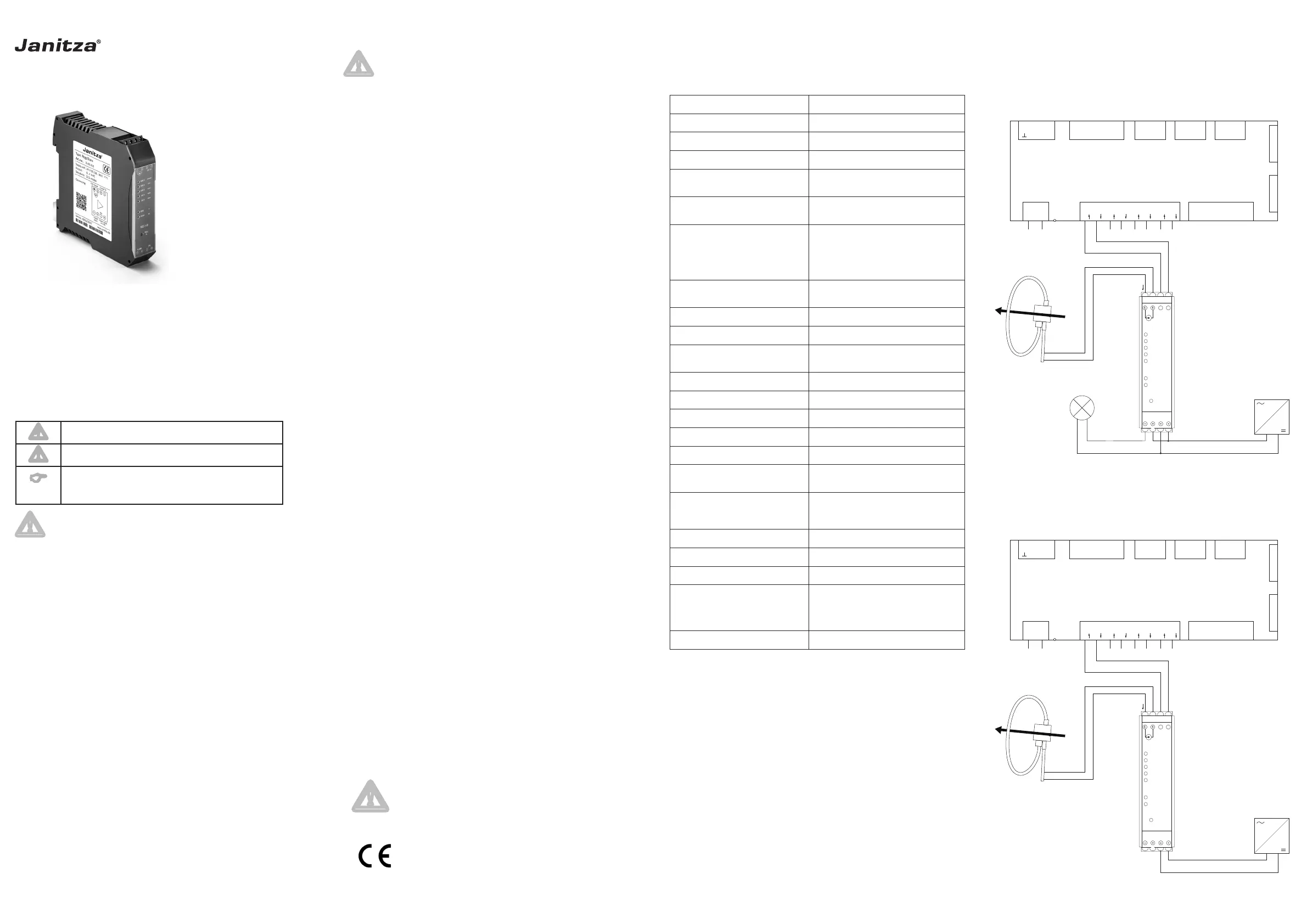
Anschlussbeispiele an ein UMG 512-PRO
Art.-Nr: 33.03.359 Dok.-Nr. 2.353.048.1.a 02/2019
4000AOVERLOAD
2000A
1000A
500A
250A
LOAD ?
ERROR 1
ERROR 2
ERROR 3
PROG
ERROR
TxD
RxD
PROG
ALARM24 V
24 VAlarm
-
+
k
l
OUT 1A
UMG 512-PRO
V1
V2
V3
V4
Spannungsmessung 1-4
Voltage Input 1-4
27282930
Strommessung 1-4
Current Input 1-4
S1S2
I1
1920
S1S2
I2
2122
S1S2
I3
2324
S1S2
I4
2526
V
N
31
Hilfsenergie
Auxiliary Supply
1718
L/+N/-
PE
RS485
8910
Temp.
4567
RCM
I
5I6
111213
Digital
Outputs
141516
Digital
Inputs
Ethernet
10/100Base-T
RJ45
Profibus
DSUB-9
23
AB
1
klS
Schwarz / Black
Weiß / White
Janitza
®
RogoTrans
Janitza
®
Rogowski-Stromwandler
Janitza
®
Rogowski current transformer
I
P
4000AOVERLOAD
2000A
1000A
500A
250A
LOAD ?
ERROR 1
ERROR 2
ERROR 3
PROG
ERROR
TxD
RxD
PROG
ALARM24 V
24 V
-
+
k
l
OUT 1A
UMG 512-PRO
V1
V2
V3
V4
Spannungsmessung 1-4
Voltage Input 1-4
27282930
Strommessung 1-4
Current Input 1-4
S1S2
I1
1920
S1S2
I2
2122
S1S2
I3
2324
S1S2
I4
2526
V
N
31
Hilfsenergie
Auxiliary Supply
1718
L/+N/-
PE
RS485
8910
Temp.
4567
RCM
I
5I6
111213
Digital
Outputs
141516
Digital
Inputs
Ethernet
10/100Base-T
RJ45
Profibus
DSUB-9
23
AB
1
klS
I
P
Janitza
®
Rogowski-Stromwandler
Janitza
®
Rogowski current transformer
Janitza
®
RogoTrans
Schwarz / Black
Weiß / White
• LED Anzeige Strombereich
4000 A
2000 A
1000 A
500 A
250 A
• LED PROG Programmiermodus
• LED ERROR Fehleranzeige
• PROG 3s
• Alarmausgang - und +
• Spannungsversorgung
24 V GND - und +
• LED Anzeige Strombereich
4000 A
2000 A
1000 A
500 A
250 A
• LED PROG Programmiermodus
• LED ERROR Fehleranzeige
• PROG 3s
• Alarmausgang - und +
• Spannungsversorgung
24 V GND - und +
Product specificaties
| Merk: | Janitza |
| Categorie: | Meetapparatuur |
| Model: | RCM 201-ROGO |
Heb je hulp nodig?
Als je hulp nodig hebt met Janitza RCM 201-ROGO stel dan hieronder een vraag en andere gebruikers zullen je antwoorden
Handleiding Meetapparatuur Janitza

15 Januari 2026
16 September 2025
9 Mei 2025
6 Mei 2025
6 Mei 2025
18 November 2024
18 November 2024
28 Februari 2024
28 Februari 2024
28 Februari 2024
Handleiding Meetapparatuur
Nieuwste handleidingen voor Meetapparatuur
3 Juni 2026
3 Juni 2026
2 Juni 2026
2 Juni 2026
2 Juni 2026
2 Juni 2026
2 Juni 2026
1 Juni 2026
1 Juni 2026
1 Juni 2026