Hifonics HCC-2000.1D Handleiding
Bekijk gratis de handleiding van Hifonics HCC-2000.1D (2 pagina’s), behorend tot de categorie Keverőgép. Deze gids werd als nuttig beoordeeld door 84 mensen en kreeg gemiddeld 5.0 sterren uit 7 reviews. Heb je een vraag over Hifonics HCC-2000.1D of wil je andere gebruikers van dit product iets vragen? Stel een vraag
Pagina 1/2
Place terminal in a secure
position so that it won’t
accidentally contact the
negative battery post
Power cable size
and fusing
It is critical to use the proper power
and ground cable. Select the size
listed here for your amplier model.
Always use high quality copper
cable. Visit our website for multi amp
system cable recommendations.
Be sure to use the proper fuse size
for each model. Some models require
an external fuse.
Properly route power,
speaker and RCA cables
through the vehicle.
Choose a mounting location
that will provide adequate air
ventilation. Mount the amplier to
a secure surface. Do not mount
the amplier upside down.
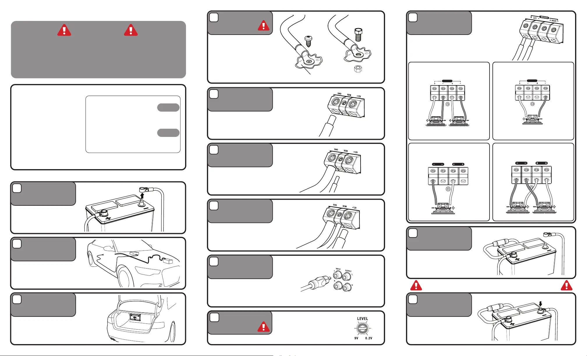
Attach the chassis ground
cable to the amplier
negative terminal. It is
important to make sure this
connection is very tight.
Bare metal
Attach the main power cable
to the amplier +12V. The
cable must run directly to
the battery and be properly
fused and be very tight.
Attach the remote turn on
wire to the amplier remote
output of the source unit.
Connect the RCA cables to
the INPUT connectors. The
OUTPUT can be used to
provide input for a second
amplier.
Connect the power cable to the
positive battery terminal. The
power cable must be fused
within 18 inches of the battery
terminal.
Re-connect the negative
battery terminal making sure it
is securely tightened.
Connect the speaker cables to
the speaker output connectors.
Follow the diagram below
that best ts your speaker
conguration.
The chassis ground connection
is critical to the performance
of the amplier. Choose a
location that is close to the
amplier. Completely scrape
away the paint and use a nut
and bolt if possible.
DO NOT USE AN EXISTING
FACTORY BOLT!
Disconnect
negative battery
terminal
Run Cables
Mount Amplier
Negative Power
Connection
Positive Power
Connection
Remote Turn-on
Connection
Signal Input
Connection
Positive Battery
Connection
Re-connect
Negative Battery
Terminal
Speaker
Connections
Chassis Ground
Be prepared to disarm your vehicle’s alarm and
to enter your radio / source unit code.
Stereo
Installation
Before you start
Monoblock
single wooferMonoblock multiple woofers
Bridged
CAUTION
Many new and factory radios require a reset code when
disconnected from battery power. This is an anti-theft
feature. Before unplugging power, you must determine if
your radio/source unit requires a reset code. Check the
operation manual for your vehicle or contact the dealer.
1
2
3
5
7
6
8
11
12
104
POWER
POWER
POWER
POWER
Turn the LEVEL control completely
counter-clockwise to minimum.
Level Control
9
0ga
4ga
BRIDGED
CH1CH2
BRIDGED
CH1CH2
SPEAKEROUTPUT
SPEAKEROUTPUT
SPEAKEROUTPUT
SPEAKEROUTPUTSPEAKEROUTPUT
SPEAKEROUTPUT
SPEAKER
LEFTRIGHT
BRIDGED
OUTPUT
SPEAKER
LEFTRIGHT
BRIDGED
OUTPUT
SPEAKER
LEFTRIGHT
BRIDGED
OUTPUT
SPEAKER
LEFTRIGHTCH1/2CH3/4
CH3/4
BRIDGED
OUTPUT
SPEAKER
LEFTRIGHT
BRIDGED
SpeakersSubwoofer
OUTPUT
SPEAKER
CH 1
CH 2
BRIDGED
CH 3
CH 4
BRIDGED
OUTPUT
SPEAKEROUTPUT
CH 3
CH 4
BRIDGED
SPEAKEROUTPUT
CH 1
CH 2
SPEAKEROUTPUT
CH 3
CH 4
SPEAKEROUTPUT
CH 5
SPEAKER
LEFTRIGHT
BRIDGED
OUTPUT
SPEAKEROUTPUT
SPEAKEROUTPUT
SpeakersSubwoofer
CH 1
CH 2
CH 3
CH 4
CH 5
BRIDGED
CH1CH2
BRIDGED
CH3CH4
BRIDGED
CH1CH2
BRIDGED
CH3CH4
SPEAKEROUTPUT
BRIDGED
CH1CH2
BRIDGED
CH1CH2
SPEAKEROUTPUT
SPEAKEROUTPUT
SPEAKEROUTPUT
SPEAKEROUTPUTSPEAKEROUTPUT
SPEAKEROUTPUT
SPEAKER
LEFTRIGHT
BRIDGED
OUTPUT
SPEAKER
LEFT
RIGHT
BRIDGED
OUTPUT
SPEAKER
LEFTRIGHT
BRIDGED
OUTPUT
SPEAKER
LEFTRIGHTCH1/2CH3/4
CH3/4
BRIDGED
OUTPUT
SPEAKER
LEFTRIGHT
BRIDGED
SpeakersSubwoofer
OUTPUT
SPEAKER
CH 1
CH 2
BRIDGED
CH 3
CH 4
BRIDGED
OUTPUT
SPEAKEROUTPUT
CH 3
CH 4
BRIDGED
SPEAKEROUTPUT
CH 1
CH 2
SPEAKEROUTPUT
CH 3
CH 4
SPEAKEROUTPUT
CH 5
SPEAKER
LEFTRIGHT
BRIDGED
OUTPUT
SPEAKEROUTPUT
SPEAKEROUTPUT
SpeakersSubwoofer
CH 1
CH 2
CH 3
CH 4
CH 5
BRIDGED
CH1CH2
BRIDGED
CH3CH4
BRIDGED
CH1CH2
BRIDGED
CH3CH4
SPEAKEROUTPUT
BRIDGED
CH1CH2
BRIDGED
CH1CH2
SPEAKEROUTPUT
SPEAKEROUTPUT
SPEAKEROUTPUT
SPEAKEROUTPUTSPEAKEROUTPUT
SPEAKEROUTPUT
SPEAKER
LEFTRIGHT
BRIDGED
OUTPUT
SPEAKER
LEFTRIGHT
BRIDGED
OUTPUT
SPEAKER
LEFTRIGHT
BRIDGED
OUTPUT
SPEAKER
LEFT
RIGHTCH1/2
CH3/4
CH3/4
BRIDGED
OUTPUT
SPEAKER
LEFTRIGHT
BRIDGED
SpeakersSubwoofer
OUTPUT
SPEAKER
CH 1
CH 2
BRIDGED
CH 3
CH 4
BRIDGED
OUTPUT
SPEAKEROUTPUT
CH 3
CH 4
BRIDGED
SPEAKEROUTPUT
CH 1
CH 2
SPEAKEROUTPUT
CH 3
CH 4
SPEAKEROUTPUT
CH 5
SPEAKER
LEFTRIGHT
BRIDGED
OUTPUT
SPEAKEROUTPUT
SPEAKEROUTPUT
SpeakersSubwoofer
CH 1
CH 2
CH 3
CH 4
CH 5
BRIDGED
CH1CH2
BRIDGED
CH3CH4
BRIDGED
CH1CH2
BRIDGED
CH3CH4
SPEAKEROUTPUT
HCC-1700.4
HCC-1500.1D
HCC-2000.1D
HCC-2500.1D
HCC-3000.1D
HCC-4200.1D
100A
50A x 2
60A x 2
External 150A
External 250A
External 300A
ModelFuseCable
Mono Block
4-Channel Mixed Mono
HF-U-01
4-Channel Full Range
Product specificaties
| Merk: | Hifonics |
| Categorie: | Keverőgép |
| Model: | HCC-2000.1D |
Heb je hulp nodig?
Als je hulp nodig hebt met Hifonics HCC-2000.1D stel dan hieronder een vraag en andere gebruikers zullen je antwoorden
Handleiding Keverőgép Hifonics

19 Maart 2026
18 Maart 2026
17 Maart 2026
17 Maart 2026
17 Maart 2026
17 Maart 2026
17 Maart 2026
17 Maart 2026
17 Maart 2026
16 Maart 2026
Handleiding Keverőgép
Nieuwste handleidingen voor Keverőgép
10 Juli 2026
10 Juli 2026
9 Juli 2026
9 Juli 2026
8 Juli 2026
8 Juli 2026
8 Juli 2026
8 Juli 2026
7 Juli 2026
7 Juli 2026