Hager HIC490E Handleiding
Hager Niet gecategoriseerd HIC490E
Bekijk gratis de handleiding van Hager HIC490E (5 pagina’s), behorend tot de categorie Niet gecategoriseerd. Deze gids werd als nuttig beoordeeld door 13 mensen en kreeg gemiddeld 4.9 sterren uit 8 reviews. Heb je een vraag over Hager HIC490E of wil je andere gebruikers van dit product iets vragen? Stel een vraag
Pagina 1/5
6H5570-50B
2. Power terminal connections
Use terminal lugs, rigid or exible busbars.
Orientation
RecommendedOK
OKNO
1. Installation
Ensure that the product is installed
on a at rigid surface.
4.
3.
6LE007790Aa
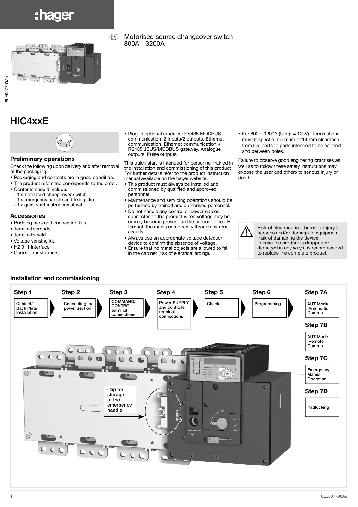
HIC4xxE
Preliminary operations
Check the following upon delivery and after removal
of the packaging:
• Packaging and contents are in good condition.
• The product reference corresponds to the order.
• Contents should include:
- 1 x motorised changeover switch
- 1 x emergency handle and xing clip
- 1 x quickstart instruction sheet.
Accessories
• Bridging bars and connection kits.
• Terminal shrouds.
• Terminal shield.
• Voltage sensing kit.
• HZI911 interface.
• Current transformers.
• Plug-in optional modules: RS485 MODBUS
communication, 2 inputs/2 outputs, Ethernet
communication, Ethernet communication +
RS485 JBUS/MODBUS gateway, Analogue
outputs, Pulse outputs.
This quick start is intended for personnel trained in
the installation and commissioning of this product.
For further details refer to the product instruction
manual available on the hager website.
• This product must always be installed and
commissioned by qualied and approved
personnel.
• Maintenance and servicing operations should be
performed by trained and authorised personnel.
• Do not handle any control or power cables
connected to the product when voltage may be,
or may become present on the product, directly
through the mains or indirectly through external
circuits.
• Always use an appropriate voltage detection
device to conrm the absence of voltage.
• Ensure that no metal objects are allowed to fall
in the cabinet (risk of electrical arcing).
• For 800 – 3200A (Uimp = 12kV). Terminations
must respect a minimum of 14 mm clearance
from live parts to parts intended to be earthed
and between poles.
Failure to observe good enginering practises as
well as to follow these safety instructions may
expose the user and others to serious injury or
death.
Installation and commissioning
Risk of electrocution, burns or injury to
persons and/or damage to equipment.
Risk of damaging the device.
In case the product is dropped or
damaged in any way it is recommended
to replace the complete product
.
Step 1
Cabinet/
Back Plate
Installation
Step 2
Connecting the
power section
Step 3
COMMAND/
CONTROL
terminal
connections
Step 4
Power SUPPLY
and controller
terminal
connections
Step 5
Check
Step 6
Programming
Step 7A
AUT Mode
(Automatic
Control)
Step 7B
AUT Mode
(Remote
Control)
Step 7C
Emergency
Manual
Operation
Step 7D
Padlocking
z
Motorised source changeover switch
800A - 3200A
1
Preferred source
2
Alternate source
&Position 0 order
éPosition 1 order
" Position 2 order
'Zero position priority order
(Remote control enable (priority over auto)
§Product available output (Motor)
èPosition II aux contact
!Position I aux contact
çPosition 0 aux contact
aO/P to HZI911 remote display
zProgrammable output contact, by default set
to ATS product available - Normally open
e to yprogrammable inputs 1-4
u and iprogrammable inputs 5-6
oAux. supply (207/210) to be used with
optional I/O modules
pContact “Start/Stop Genset”: if S1 is not
available the NC contact (71-72) is closed
qContact “Start/Stop Genset”: if S1 is not
available the NO contact (71-74) is open
sOption module slots 1 to 4
dCurrent Transformer incoming cable
connections
fVoltage sensing inputs
gPower supply inputs
Example: control wiring for a 400 VAC application having a 3 phase and neutral supply
3. CONTROL/COMMAND terminals
Ensure that the product is in Manual Mode.
ff
gg
HZI911
4. Power supply, sensing and control wiring
Use cables with 1,5 to 2,5 mm
2
section.Screw M3Tightening torque: min.: 0.5 Nm - max.: 0.6 Nm
+=,
%%
3RZHU9a
3RZHU9a
ATS Power supply input II
Power supply II - L
Power supply II - N
208-277 VAC ±20% : 50/60 Hz
ATS Voltage sensing input
Source supply II
S II - Phase 1
S II - Phase 2
S II - Phase 3
575 VAC (ph-ph) maxi
S II - Neutral
332 VAC (ph-n) maxi
Programmable inputs
To option module (-)/Common
Progr. inputs (208-209)
To option module (+)
Genset Start/stop
NC
Common
NO
ATS Power supply input I
Power supply I - L
Power supply I - N
208-277 VAC ±20% : 50/60 Hz
ATS Voltage sensing input
Source supply I
S I - Phase 1
S I - Phase 2
S I - Phase 3
575 VAC (ph-ph) maxi
S I - Neutral
332 VAC (ph-n) maxi
ATS Module control inputs
(programmable)
ATS Module output control
(programmable)
Remote interface
RJ45 to HZI911
Current transformer incoming
cable connections
Slot for optional modules
5. Check
Whilst in manual mode,
check the wiring
and if ok power up
the product.
LED Green =
“Power”: ON
LED Red =
“Manuel/Defaut”: ON
800 A1000
A
1250
A
1600 A2000 A2500 A3200 A
Minimum Cu
cable section
at Ith
(mm
2
)
2x185-
Minimum Cu
busbar section
at Ith
(mm
2
)
2x50x52x63x52x63x72x100x53x100x52x100x103x100x10
Maximum Cu
cable section
(mm
2
)
4x1856x185-
Maximum Cu
busbar width
(mm)
63100
Type of screw
M8M10M12
Recommended
tightening
torque
(N.m)
8,32040
Maximum
tightening
torque
(N.m)
132645
Dimensions in mm
Door cut-out for front panel
2000A to 3200A
800A to 1600A
338.58.5
50
3310
ø 9
ø 15
800A to 1000A
16 x 11
60
28.515.7515.75
28.515
1250A
15
5
5
12.5
25
25
30
30
45
45
90
ø12.5
1600A to 3200A
T
250
C2
1
280
C21
250
M
T
51,5
M51.5
800A1000A1250A1600A2000A2500A3200A
4P
M
335467
T
80120
C
391523
Clip for
storage
of the
emergency
handle
6LE007790Aa16LE007790Aa26LE007790Aa3
Product specificaties
| Merk: | Hager |
| Categorie: | Niet gecategoriseerd |
| Model: | HIC490E |
Heb je hulp nodig?
Als je hulp nodig hebt met Hager HIC490E stel dan hieronder een vraag en andere gebruikers zullen je antwoorden
Handleiding Niet gecategoriseerd Hager

12 Mei 2025
12 Mei 2025
12 Mei 2025
12 Mei 2025
12 Mei 2025
12 Mei 2025
12 Mei 2025
12 Mei 2025
12 Mei 2025
12 Mei 2025
Handleiding Niet gecategoriseerd
Nieuwste handleidingen voor Niet gecategoriseerd
23 Juli 2026
23 Juli 2026
23 Juli 2026
23 Juli 2026
23 Juli 2026
23 Juli 2026
23 Juli 2026
23 Juli 2026
23 Juli 2026
22 Juli 2026