Futaba 9ZHP_part2 Handleiding

Futaba Radio controll 9ZHP_part2

Lees hieronder de 📖 handleiding in het Nederlandse voor Futaba 9ZHP_part2 (78 pagina's) in de categorie Radio controll. Deze handleiding was nuttig voor 28 personen en werd door 2 gebruikers gemiddeld met 4.5 sterren beoordeeld

Pagina 1/78
Airplane Section
SAMPLE AIRPLANE SETUP INSTRUCTIONS
The
following example shows how the PCM
1024Z may be programmed for a pattern airplane.
The settings presented here are for a typical
model. Your model's settings are likely to vary
from these, but the procedures given will still be
applicable.
1. Model Selection
Use the Model Select function MSL to select a
vacant model memory (or one you don't mind erasing)
and choose the AIRPLANE Setup using the Type
TYP
function from Model menu.
2. Name The New Model
Rename the model using the Model Name MNA
function in the model menu. Switch to the Condition
menu
CND
and name the default flight condition
(we recommend NORM L). Later you may add other
flight conditions, which may also be named to make
them easier to identify.
3. Activate Special Mixing
Activate Flaperon
FPN
or Aileron Diferential
ADF
if you desire these functions (you may only
choose one; both require two aileron servos). FPN is
suggested since it can accommodate differential
through end point adjustments, and has Flap mixing.
The Flap mixing is used to have the ailerons behave as
flaps as well, which can be used to make tighter loops
and squarer corners in maneuvers. Use ALV to get
elevators that act as ailerons (two servos are required
for ALV function). You need not adjust the throws
and mixing ratios at this time.
4. Reset Control Order
If necessary, reset the Control Order using the
Function Control
FNC
in the model menu. Here you
may choose what sticks and sliders control the dif-
ferent functions. If you use the ALV function, move
the retract operation to another switch, perhaps CH7
orCH8.
5. Connect Servos
Plug Servos into Correct Channel Numbers
1. AIL Aileron (Ail 1 if FPN or ADF on)
2. ELE Elevator
3. THR Throttle
4. RUD Rudder
5. GEA Landing Gear (Elev 2 if ALV on)
6. FLP Flap (Ail 2 if FPN activated)
7. AU1
Spoiler (Ail 2 if ADF is used)
8. AU2 Collective Pitch
9. CH9
Channel 9
6. Set Neutral Points
Use the Subtrim function
STM
to move each
servo to its neutral position. If the amount of subtrim
is large, you should reset the subtrim to zero and move
the splined servo arm to a position that is as close to
the desired neutral as possible. Then use the subtrim
to get the neutral position "right on." Repeat with the
remaining channels.
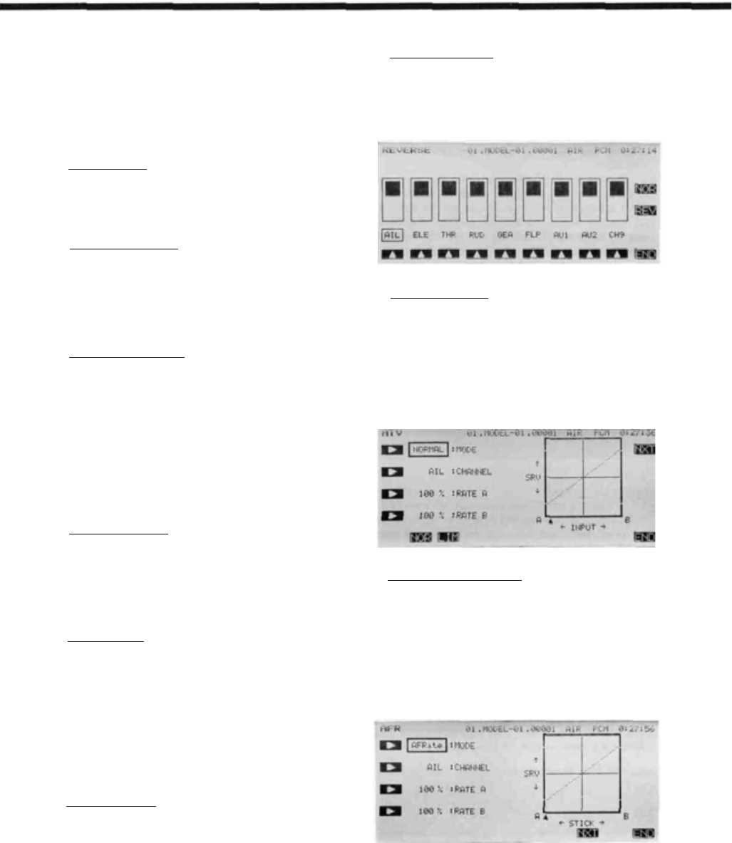
7. Adjust Servo Throws
Check the proper direction of throw for each
servo. Use Reversing Function
REV
in the Model
menu to set proper throw directions for each servo.
Double check that each servo moves the proper direc-
tion.
8. Limit Servo Throws
Now use the ATV function to limit servo throws.
The travel of the ailerons should be limited to roughly
10—12° maximum in both directions with the ATV
function. Repeat for elevator. Adjust rudder lateral
motion to about ±45°. Be sure that no servo "bottoms
out" at maximum control throw. After setting maxi-
mum throws, ATV is rarely used. Instead use AFR in
the different flight modes.
9. Changing The Control Feel
If you would like to soften the control feel for
ailerons, use the AFR menu. Press the
NXT
key,
then the
EX1
key to get exponential curve. Set a
rate of -15% to -25%. EX2 is used for throttle only.
Change to Elevator using the Channel key. Use the
AFR to get slightly more up than down travel, and use
EX1 with a -10% setting.
Change to Rudder with the Channel key, and set
EX1
for-10%.
Airplane Section, Page 77
Airplane Section
10. Set Flaperon Throws
Now go back to the FPN (Flaperon) menu. Set
differential by limiting the down aileron throws on
both sides. The down throw should be set between
70% and 95% of the up throw. This setting depends on
the individual model and its particular flight character-
istics, so make changes after flight testing. Be sure
that the flap mixing settings are the same (default is
±100%).
Move to the E->F menu to set up how much the
ailerons move due to elevator. Approximately 10-
30% up and down mixing should be used (be sure that
up elevator causes the ailerons to drop, and down
elevator raises the ailerons up). The amount of aileron
droop at neutral elevator may be set with the A knob.
You may adjust this travel by adjusting the trim rate —
it can be set to zero to prevent accidental changes (be
sure this knob is zeroed before resetting subtrims).
Using the
SWT
button, you can also define a switch
to turn the elevator-flaperon mixing on and off.
11. Setting Up Airbrakes
To make landings easier, you may set a switch to
move both the elevators and flaps to a preset position
for an airbrake effect. Normally, the ailerons are raised
5—10° and the elevator is offset to cancel any trim
change.
Call the Airbrake
ABK
function from the con-
dition menu. Select the Manual mode by pressing the
MAN
key. Auto is available.
This system should normally be used in manual
mode. To select the operating switch, press the
SWT
key. The display shows that the default airbrake con-
trol switch is the C switch, ON in the lower position.
You may choose another switch or direction at this
time. Verify proper operation of the switch by activat-
ing it and watching the servos move.
Press the
PRE
key to get back to the preceding
key. If you have spoilers, they may be actuated also.
Read the section on ABK for more details.
12. Snap Roll Setup
You may have any switch activate the Snap Roll
function (the spring-loaded switch is strongly recom-
mended!). Call the Snap Roll function
SNP
form
the Condition menu. Activate it with the
ACT
key.
Set the deflection for each switch position: ailerons
±100-110%, elevator ±80-100%, rudder ±70-80%.
Be sure to choose the correct directions with the
For safety, you may also turn on the safety switch
using the O button. This safety inhibits the activation
of snap roll if the landing gear are down. Check to
make sure the switch is set for the correct direction.
13. Setting Up Differential Elevator
Your PCM 1024Z system has a unique function
called ALV for "Ailevators," or differential elevators.
This function provides roll control whenever the
propeller slipstream is acting on the tail, and is effec-
tive at low airspeeds.
Press the
ALV
key to enter the menu. Activate
with the
ACT
key, then adjust the rates given by the
A-3 and A-4 settings. We recommend starting out with
small deflections at first. Be sure that the settings for
ELE are 100% to get full elevator authority.
Airplane Section, Page 78
Airplane Section
14.
Flight Conditions Switching
If you like, you may set up the system to call up
more than one function or switch to a new set of trims
or control settings simultaneously by moving a single
switch. You can have different subtrims, coupling,
differential, exponentials, and throw volumes. In fact
you may change EVERY parameter between flight
modes.
We recommend that you fly the model and adjust
trims and control responses to your liking before
defining another flight condition. Any bad tendencies
may be corrected with custom programmable mix
settings
PMX
. Then, copy the set of adjustments to
a new flight condition, where they may be modified
for the new desired conditions. After copying you
may add new functions as necessary.
Use the Condition Select
CSL
button in the
Model Menu. This function allocates the necessary
number of flight conditions to the model memory.
Note the condition number next to the D (default) in
the display. This is the set of conditions that will be
copied into a new condition and modified. Also note
the number after the next display. You will copy to
this condition.
Use the Copy Condition
CPC
from the System
menu. This function copies the contents of one condi-
tion into another. Choose the default flight condition
number, press the SET button, then choose the second
condition number in the lower box "TO CONDI-
TION." Give the command to copy.
15.
Volume Setting
Some functions can have their mixing ratio vary
with the motion of another slider or knob: use the
VOL key O to get to this choice (for example, see
ADF). Move the selected control to determine how it
affects the mix. You can also add a time delay on
many of the menus: look for a DELAY setting.
16. Programmable Mixers
Up to five mixers are available in all flight condi-
tions. These may be used to enhance flight capabilities
or to correct bad tendencies by adjusting mixing from
one control to another. For example, you may use
Elevator->Flap coupling to tighten up the corners on
square loops, Throttle->Rudder coupling to correct
for torque tendencies, etc. There is no limit to the
number of corrections that can be made.
Your PCM 1024Z system is filled with powerful,
predefined mixing functions. Be sure to browse through
the various function menus in the Aircraft section follow-
ing this example.
The switch that calls the flight conditions should
be selected. Return to the Condition Select
CSL
function, press the desired flight condition number,
and use the SWT button to choose the desired switch
location. Once you have selected a condition, use the
CNA (Condition NAme) button to label the new con-
dition (you may have to flip the chosen switch to the
correct position to get the desired condition). Now,
you may go through the Condition menu items to get
the desired settings in the new mode. Read the condi-
tion name after the model name to be sure you are
changing the condition you want.
Airplane Section, Page 79


Product specificaties

Merk: Futaba
Categorie: Radio controll
Model: 9ZHP_part2

Heb je hulp nodig?

Als je hulp nodig hebt met Futaba 9ZHP_part2 stel dan hieronder een vraag en andere gebruikers zullen je antwoorden