Flir Grasshopper2 Handleiding
Flir Niet gecategoriseerd Grasshopper2
Bekijk gratis de handleiding van Flir Grasshopper2 (2 pagina’s), behorend tot de categorie Niet gecategoriseerd. Deze gids werd als nuttig beoordeeld door 72 mensen en kreeg gemiddeld 4.6 sterren uit 8 reviews. Heb je een vraag over Flir Grasshopper2 of wil je andere gebruikers van dit product iets vragen? Stel een vraag
Pagina 1/2
Wi
Wi
Wi
WiWil
l
l
lll
l
l
ll y
y
y
yyou
ou
ou
ouour
r
r
rr s
s
s
ssy
y
y
yys
s
s
sstem
tem
tem
temtem s
s
s
ssup
up
up
upupport
port
port
portport t
t
t
tthe
he
he
hehe
c
c
c
ccam
am
am
amamera?
era?
era?
era?era?
D
D
D
DDo
o
o
oo y
y
y
yyou
ou
ou
ouou h
h
h
hhav
av
av
avave
e
e
ee a
a
a
aa downl
downl
downl
downldownloads
oads
oads
oadsoads ac
ac
ac
acacc
c
c
ccou
ou
ou
ouount?
nt?
nt?
nt?nt? D
D
D
DDo
o
o
oo y
y
y
yyou
ou
ou
ouou ha
ha
ha
hahav
v
v
vve
e
e
ee al
al
al
alall
l
l
ll the
the
the
thethe pa
pa
pa
paparts
rts
rts
rtsrts y
y
y
yyou
ou
ou
ouou nee
nee
nee
neeneed?
d?
d?
d?d?
Recommended System Configuration:
nOS—Vista SP1, Windows7
nCPU—Intel Core2 dual
nRAM—2 GB
nVideo—PCIExpress128 MB
nPorts—GigE
nSoftware—MicrosoftVisual Studio2005 SP1 and
SP1UpdateforVista(to compileand run example
code using FlyCapture)
Thepagehas manyresources tohelpPointGrey downloads
youoperate your camera effectively,including:
nSoftware, includingDrivers(required forinstallation)
nFirmwareupdatesandrelease notes
nDimensional drawings andCADmodels
nDocumentation
To access the downloadsresources youmusthave a
downloads account.
1.Gotothe PointGrey downloads page.
2.Under Register(New Users), complete the form,then
click .Submit
Afteryou submityour registration, you willreceiveanemail
withinstructions onhowtoactivate youraccount.
Toinstall yourcamerayouwill needthefollowing
components:
nEthernet cable
n8-pin GPIOcable
nC-mount Lens
nTripodadapter (optional)
nInterface card
PointGreysells anumberoftheadditional parts
required forinstallation.Topurchase,visitthePoint
GreywebsiteAccessories page.
GettingStartedwith the
Grasshopper2GigE DigitalCamera
For
For
For
ForFor M
M
M
MMore
ore
ore
oreore Inform
Inform
Inform
InformInformati
ati
ati
atiation
on
on
onon
For moreinformation about...See...
Yourcamera'ssettingsand capabilitiesTechnicalReferenceManual
Using the GigEConfiguratorthe Online Help includedwith the tool
Using the FlyCap demo programthe Online Help includedwith the tool
Accessing customer downloadsKnowledge Base Article 10142
Selecting alensKnowledge Base Article 10269
Setting Up Multiple GigECamerasTechnicalApplication Note10351
TheFlyCaptureSDK help andothertechnicalreferencescan befound in the
Programs>PointGrey Research>PGRFlyCapture>Documentation directory. Our
online Knowledge Base addresses manyquestions.
C
C
C
CCam
am
am
amamera
era
era
eraera Int
Int
Int
IntInterfac
erfac
erfac
erfacerface
e
e
ee
Et
Et
Et
EtEthe
he
he
hehern
rn
rn
rnrne
e
e
eet
t
t
tt C
C
C
CCo
o
o
oon
n
n
nnn
n
n
nnect
ect
ect
ectecto
o
o
oor
r
r
rr
The8-pin RJ-45Ethernet jackisequipped withtwo (2)M2screwholesfor secure
connection.Pinassignments conformtothe Ethernetstandard.
G
G
G
GGe
e
e
een
n
n
nne
e
e
eera
ra
ra
raral
l
l
ll Purp
Purp
Purp
PurpPurpo
o
o
oose
se
se
sese I
I
I
II/
/
/
//O
O
O
OO C
C
C
CCo
o
o
oon
n
n
nnn
n
n
nne
e
e
eect
ct
ct
ctcto
o
o
oor
r
r
rr
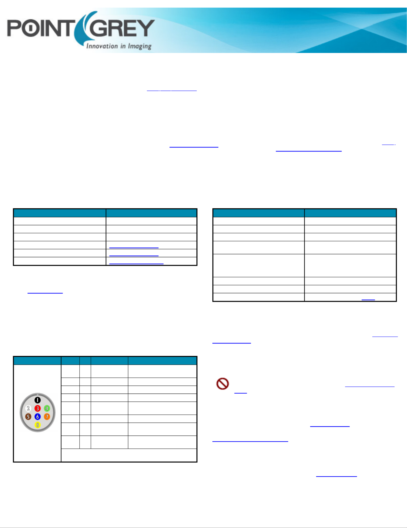
The camerahas an8-pinGPIOconnectoronthe backof the case; refertothe
diagramforwire color-coding.
DiagramColor PinFunctionDescription
Black 1I0Opto-isolated input (default Trigger
in)
White2O1Opto-isolated output
Red3IO2Input/Output/serial transmit (TX)
Green4IO3Input/Output/serialreceive (RX)
Brown 5GNDGroundfor bi-directionalIO, V
EXT, +3.3
V pins
Blue6OPTO_GNDGroundforopto-isolatedIO pins
Orange 7VEXT
Allows the camerato be powered
externally
Yellow8+3.3 VPowerexternalcircuitryupto 150 mA
To configure the GPIOpins, consultthe General Purpose Input/Output section
of yourcamera'sTechnicalReference Manual.
Status
Status
Status
StatusStatus Ind
Ind
Ind
IndIndi
i
i
iic
c
c
ccator
ator
ator
atorator LED
LED
LED
LEDLED
LEDStatus Description
OffNotreceiving power
Steady green, highintensity (~5 seconds)1. Camerapowersup
Green/Red,flashing (~2seconds)2. Cameraprograms the FPGA
Green flashing quickly, low intensity3. Establishing IP connection. The cameraattempts
to establish an IP connection in the followingorder:
One green blink(~1-2 seconds)
Two green blinks (~1-2 seconds)
Three greenblinks (~1-2 seconds)
Three redblinks (~1-2 seconds)
i)ApersistentIPaddress,if enabledandavailable;
ii) aDHCPaddress,if enabledand available;
iii) a link-localaddress(LLA).
iv) Failure toestablish connection
Steadygreen, highintensity4. Camerais streaming images
Red/Green flashing quicklyFirmware updateinprogress
Red flashing slowlyGeneral error -contact technical support
C
C
C
CCam
am
am
amamera
era
era
eraera C
C
C
CCare
are
are
areare
To cleantheimagingsurface of yourcamera,followthe stepsoutlinedin Knowledge
Base Article 10243.
Extended exposureto brightsunlight, rain, dusty environments, etc. may cause
problems withthe electronics andoptics of the system.
Avoid excessiveshaking, dropping, or mishandlingofthedevice.
Do notopen thecamera housing.Doing so voids the HardwareWarranty.
Avoid electrostatic charging.Formoredetails,consultKnowledgeBase Article
10147.
Contacting PointGrey Research
Forallgeneralquestionspleasecontact usat info@ptgrey.com.
Fortechnicalsupport(existing customers only) contactus at
www.ptgrey.com/support/ticket/.
Main Office:
Mailing Address:
PointGrey Research,Inc.
12051 RiversideWay
Richmond, BC, CanadaV6W1K7
Tel: +1 (604)242-9937
TollFree +1 (866)765-0827
(North America only)
Fax: +1 (604)242-9938
Email: sales@ptgrey.com
Product specificaties
| Merk: | Flir |
| Categorie: | Niet gecategoriseerd |
| Model: | Grasshopper2 |
Heb je hulp nodig?
Als je hulp nodig hebt met Flir Grasshopper2 stel dan hieronder een vraag en andere gebruikers zullen je antwoorden
Handleiding Niet gecategoriseerd Flir

29 December 2026
7 December 2025
5 December 2025
5 December 2025
5 December 2025
4 December 2025
4 December 2025
4 December 2025
1 December 2025
30 November 2025
Handleiding Niet gecategoriseerd
Nieuwste handleidingen voor Niet gecategoriseerd
8 Juni 2026
8 Juni 2026
8 Juni 2026
8 Juni 2026
8 Juni 2026
8 Juni 2026
8 Juni 2026
8 Juni 2026
8 Juni 2026
8 Juni 2026