Flir Chameleon3 Handleiding
Flir Niet gecategoriseerd Chameleon3
Bekijk gratis de handleiding van Flir Chameleon3 (2 pagina’s), behorend tot de categorie Niet gecategoriseerd. Deze gids werd als nuttig beoordeeld door 89 mensen en kreeg gemiddeld 4.9 sterren uit 9 reviews. Heb je een vraag over Flir Chameleon3 of wil je andere gebruikers van dit product iets vragen? Stel een vraag
Pagina 1/2
G
G
G
GGETTI
ETTI
ETTI
ETTIETTING
NG
NG
NGNG
STARTE
STARTE
STARTE
STARTESTARTED
D
D
DD
FLIRCHAMELEON®3
USB3
Vision
Will
Will
Will
WillWill y
y
y
yyo
o
o
oou
u
u
uur
r
r
rr syste
syste
syste
systesystem
m
m
mm sup
sup
sup
supsuppo
po
po
popor
r
r
rrt
t
t
tt the
the
the
thethe c
c
c
cca
a
a
aamera?
mera?
mera?
mera?mera?
RecommendedSystem Configuration:
nOS—Windows, Linux (32- and 64-bit)
nCPU—Intel Core 2 Duo, or equivalent
nRAM—2 GB RAM
nVideo—128 MB
nPorts—PCIe 2.0compatible hostcontrollerwithUSB3.1 connector
nSoftware—MicrosoftVisualStudio2010 (tocompile andrun example
code)
See TechnicalApplication Note 10359 forinformation onrecommended system
components forUSB3.0.
D
D
D
DDo
o
o
oo y
y
y
yyo
o
o
oou
u
u
uu h
h
h
hhav
av
av
avave
e
e
ee a
a
a
aa d
d
d
ddo
o
o
oown
wn
wn
wnwnlo
lo
lo
loloads
ads
ads
adsads a
a
a
aacc
cc
cc
cccco
o
o
oou
u
u
uunt?
nt?
nt?
nt?nt?
Our downloads page hasmany resourcestohelp you operate your camera
effectively, including:
nSoftware, including Drivers(requiredforinstallation)
nFirmwareupdates andrelease notes
nDimensional drawings andCADmodels
nDocumentation
Toaccess thedownloads resources you musthave a downloads account.
1.Go to ourwebsite: www.flir.com/iis.
2.In theupperrightcorner,click Register.
3.Complete the form, then click.Register
Afteryousubmityourregistration, you willreceive an emailwith instructionson
how to activateyouraccount.
D
D
D
DDo
o
o
oo y
y
y
yyo
o
o
oou
u
u
uu h
h
h
hhav
av
av
avave
e
e
ee a
a
a
aall
ll
ll
llll the
the
the
thethe p
p
p
ppa
a
a
aar
r
r
rrts
ts
ts
tsts y
y
y
yyou
ou
ou
ouou nee
nee
nee
neeneed?
d?
d?
d?d?
To installyourcamerayou willneed the following components:
nUSB 3.1cable
nLens
nTripod adapter(optional)
nInterface card
FLIRsells a numberoftheadditionalparts requiredforinstallation. Topurchase,
visit our Accessories page.
Ca
Ca
Ca
CaCamera
mera
mera
meramera Ca
Ca
Ca
CaCare
re
re
rere
Toclean theimaging surface ofyourcamera, followthe steps outlinedin
Knowledge Base Article 10243.
Extended exposure tobrightsunlight,rain, dusty environments, etc. maycause
problems withtheelectronics andoptics ofthesystem.
Avoid excessive shaking, dropping, ormishandling ofthe device.
Warning! Do notopen thecamera housing. Doing so voids the Hardware
Warranty.
Avoid electrostatic charging.
I
I
I
IIns
ns
ns
nsnsta
ta
ta
tatalling
lling
lling
llinglling Y
Y
Y
YYo
o
o
oou
u
u
uur
r
r
rr I
I
I
IIn
n
n
nnterf
terf
terf
terfterfac
ac
ac
acace
e
e
ee C
C
C
CCa
a
a
aar
r
r
rrd
d
d
dd a
a
a
aand
nd
nd
ndnd So
So
So
SoSof
f
f
fftware
tware
tware
twaretware
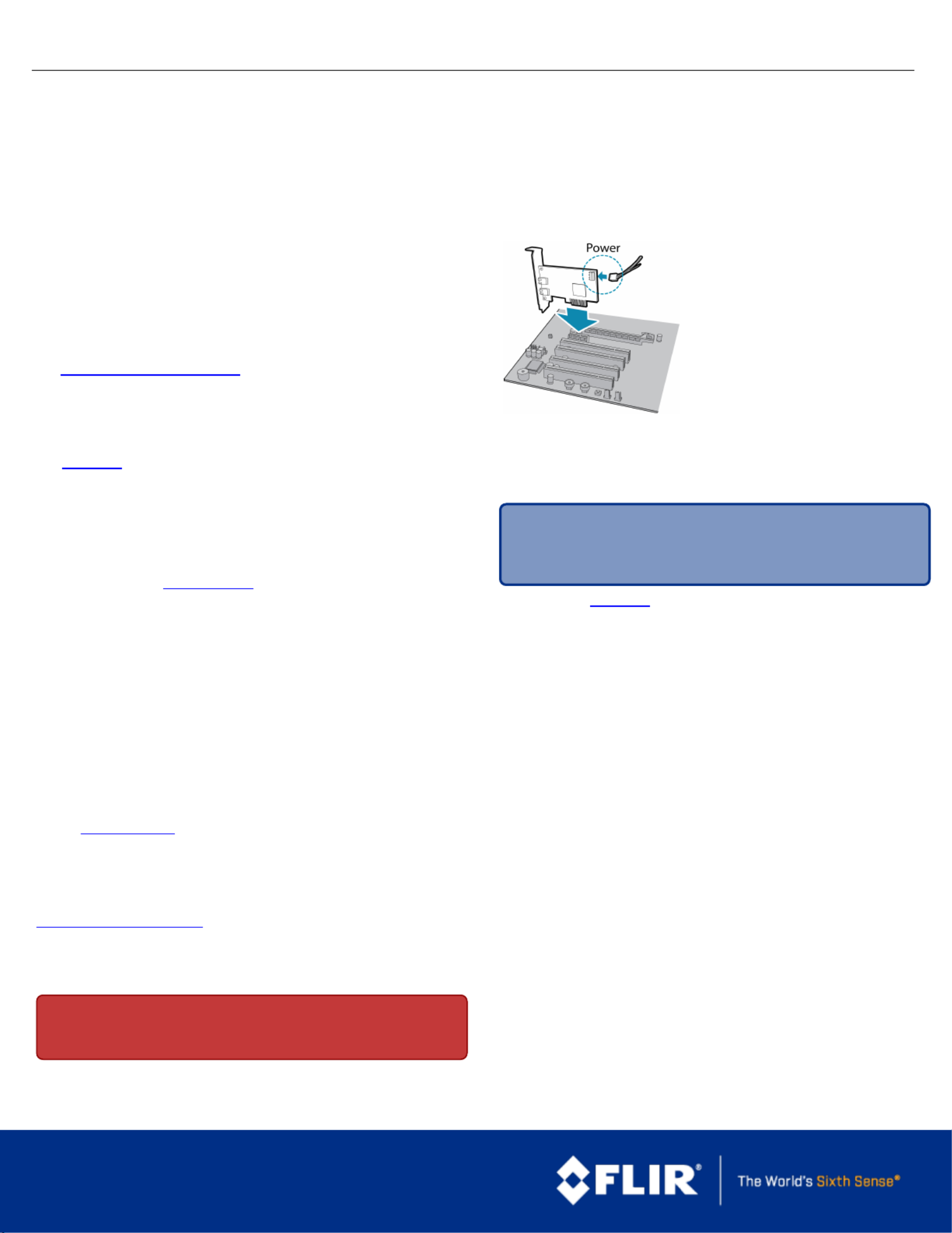
1.Install your Interface Card
Ensure the card isinstalled perthe
manufacturer's instructions.
Connecttheinternal IDEorSATApower
connectoron the card to the computer
power supply.
Alternatively,use yourPC's built-in host
controller, ifequipped.
Open theWindows Device Manager. Ensurethecard isproperlyinstalled under
Universal Serial Bus Controllers. An exclamationpoint (!) next to the card
indicatesthe driverhas notyetbeen installed.
2.Install the FlyCapture®Software
Note: Forexisting userswho alreadyhaveFlyCapture installed, we
recommend ensuring you have the latest version foroptimalperformance
ofyour camera. Ifyoudo notneedto installFlyCapture, use the
DriverControlGUI to installand enable driversforyour card.
a.Login to ourdownloads page.
b.Select yourandfromthe drop-down lists andCameraOperating System
click thebutton.Search
c.Click on theSoftware search results to expand the list.
d.Click the appropriate linkto begin the download and installation.
Afterthe download iscomplete, theFlyCapture setupwizard begins. Ifthe
wizard does notstartautomatically, double-clickthe .exe file to open it.Follow
the steps in each setupdialog.
3. Enable the Driversfor the card
Duringinstallation,you areprompted to select your interfacedriver.
In theInterface DriverSelection dialog, select the I will use USBcameras.
This selection ensures thepgrxhci(USBPro)and pgrusbcamdrivers are
installed.
To uninstallorreconfigure the driver at anytime aftersetup iscomplete, use the
DriverControlGUI.
1/26/2017
Namesand marksappearing on the productsherein are either
registered trademarks or trademarksof FLIRSystems,Inc.
and/or its subsidiaries.
© 2015-2017 FLIR Integrated Imaging Solutions Inc. Allrights
reserved.
Product specificaties
| Merk: | Flir |
| Categorie: | Niet gecategoriseerd |
| Model: | Chameleon3 |
Heb je hulp nodig?
Als je hulp nodig hebt met Flir Chameleon3 stel dan hieronder een vraag en andere gebruikers zullen je antwoorden
Handleiding Niet gecategoriseerd Flir

29 December 2026
7 December 2025
5 December 2025
5 December 2025
5 December 2025
4 December 2025
4 December 2025
4 December 2025
1 December 2025
30 November 2025
Handleiding Niet gecategoriseerd
Nieuwste handleidingen voor Niet gecategoriseerd
8 Juni 2026
8 Juni 2026
8 Juni 2026
8 Juni 2026
8 Juni 2026
8 Juni 2026
8 Juni 2026
8 Juni 2026
8 Juni 2026
8 Juni 2026