Festo SDBT-MSX-1L-PU-E-5-N-LE Handleiding
Festo Niet gecategoriseerd SDBT-MSX-1L-PU-E-5-N-LE
Bekijk gratis de handleiding van Festo SDBT-MSX-1L-PU-E-5-N-LE (3 pagina’s), behorend tot de categorie Niet gecategoriseerd. Deze gids werd als nuttig beoordeeld door 26 mensen en kreeg gemiddeld 5.0 sterren uit 4 reviews. Heb je een vraag over Festo SDBT-MSX-1L-PU-E-5-N-LE of wil je andere gebruikers van dit product iets vragen? Stel een vraag
Pagina 1/3
Translation of the original instructions
© 2019 all rights reserved to & Co. KGFesto SE
1Further applicable documents
All available documents for the product www.festo.com/pk.è
2Safety
2.1Intended use
This product is intended for sensing the position of magnets (e.g. the piston posi
tion) in Festo products. The device is intended for use in an industrial environ
ment.
2.1.1Area of application and approval
In combination with the UL inspection mark on the product, the information in this
section must also be observed in order to comply with the certification conditions
of Underwriters Laboratories Inc. (UL) for USA and Canada.
UL approval information
Product category codeNRKH, NRKH7
File numberE232949
Considered standardsUL 609471, UL 6094752
C22.2 No. 609471, C22.2 No. 6094752
UL mark
Tab. 1
Only use power sources which guarantee reliable electrical isolation of the oper
ating voltage in accordance with IEC/EN 602041. Observe also the general
requirements for PELV power circuits in accordance with IEC/EN 602041. Only for
connection to a NEC/CEC Class 2 supply. The device shall be supplied from an
isolating transformer having a secondary listed fuse rated 1 A.
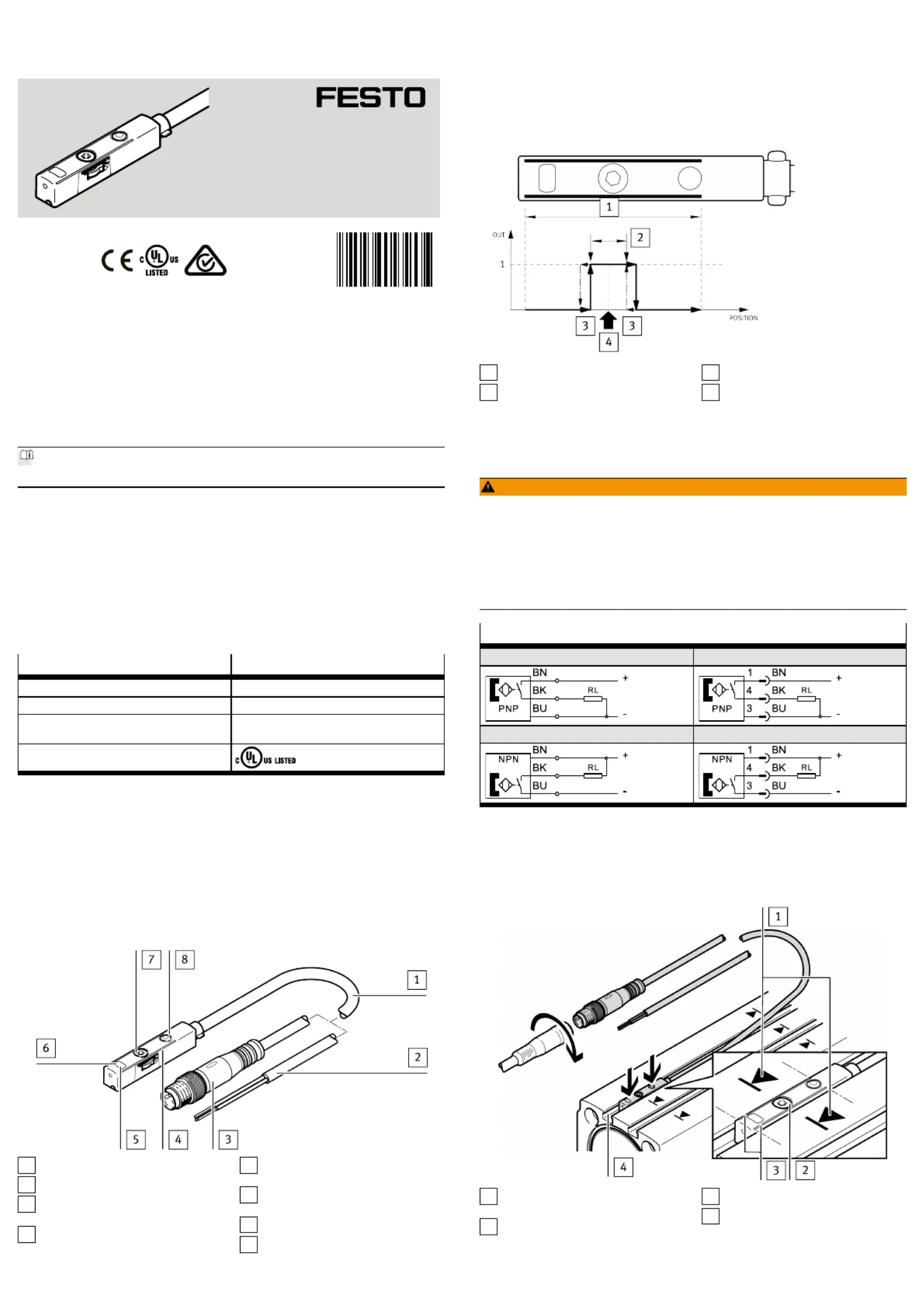
3Product overview
3.1Structure
1
Connecting cable
2
Open cable end (SDBTMSX...LE)
3
Plug connector M8
(SDBTMSX...M8)
4
Marking of sensing range
5
Green LED: display of sensing
range; only in teachin mode
6
Yellow LED: switching status dis
play
7
Retaining screw
8
Capacitive operating key
Fig. 1
3.2Function
The proximity sensor SDBTMSX detects the magnetic field of the piston magnet.
In the sensing range of the proximity switch, a switching point can be pro
grammed. To set a switching point in the sensing range of the proximity sensor,
there are two options:
–Auto teachin
–Capacitive operating key
1
Sensing range
2
Switching window
3
Hysteresis
4
Teachin point
Fig. 2
4Installation
4.1Electrical
WARNING!
Risk of injury due to electric shock.
•For the electrical power supply, use only PELV circuits in accordance with IEC
602041/EN 602041 (Protective ExtraLow Voltage, PELV).
•Observe the general requirements of IEC 602041/EN602041 for PELV cir
cuits.
•Only use voltage sources that ensure a reliable electric separation from the
mains network in accordance with IEC 602041/EN 602041.
Circuit diagrams
SDBT…PU…LESDBT…PU…M8
SDBT…NU…LESDBT…NU…M8
Tab. 2
4.2Mechanical
•Mount the proximity sensor in the end position of the piston so that the end
position is in the sensing range of the sensor. If available, the orientation aid
provides the marking of the piston end position on the drive.
1
Marking of the piston end position
on the drive (if available)
2
Retaining screw
3
Marking of sensing range
4
Tslot
Fig. 3
8125856
SDBT-MSX
Proximity Sensor
8125856
201911a
[8125858]
Instructions|Operating
Festo SE & Co. KG
Ruiter Straße 82
73734 Esslingen
Germany
+49 711 3470
www.festo.com
Product specificaties
| Merk: | Festo |
| Categorie: | Niet gecategoriseerd |
| Model: | SDBT-MSX-1L-PU-E-5-N-LE |
Heb je hulp nodig?
Als je hulp nodig hebt met Festo SDBT-MSX-1L-PU-E-5-N-LE stel dan hieronder een vraag en andere gebruikers zullen je antwoorden
Handleiding Niet gecategoriseerd Festo

3 Mei 2026
30 April 2026
29 April 2026
29 April 2026
29 April 2026
29 April 2026
28 April 2026
28 April 2026
28 April 2026
28 April 2026
Handleiding Niet gecategoriseerd
Nieuwste handleidingen voor Niet gecategoriseerd
23 Juli 2026
23 Juli 2026
23 Juli 2026
23 Juli 2026
23 Juli 2026
23 Juli 2026
23 Juli 2026
23 Juli 2026
23 Juli 2026
22 Juli 2026