Festo HMIYF-RF/DL40 Handleiding
Festo Niet gecategoriseerd HMIYF-RF/DL40
Bekijk gratis de handleiding van Festo HMIYF-RF/DL40 (238 pagina’s), behorend tot de categorie Niet gecategoriseerd. Deze gids werd als nuttig beoordeeld door 3 mensen en kreeg gemiddeld 4.6 sterren uit 8 reviews. Heb je een vraag over Festo HMIYF-RF/DL40 of wil je andere gebruikers van dit product iets vragen? Stel een vraag
Pagina 1/238
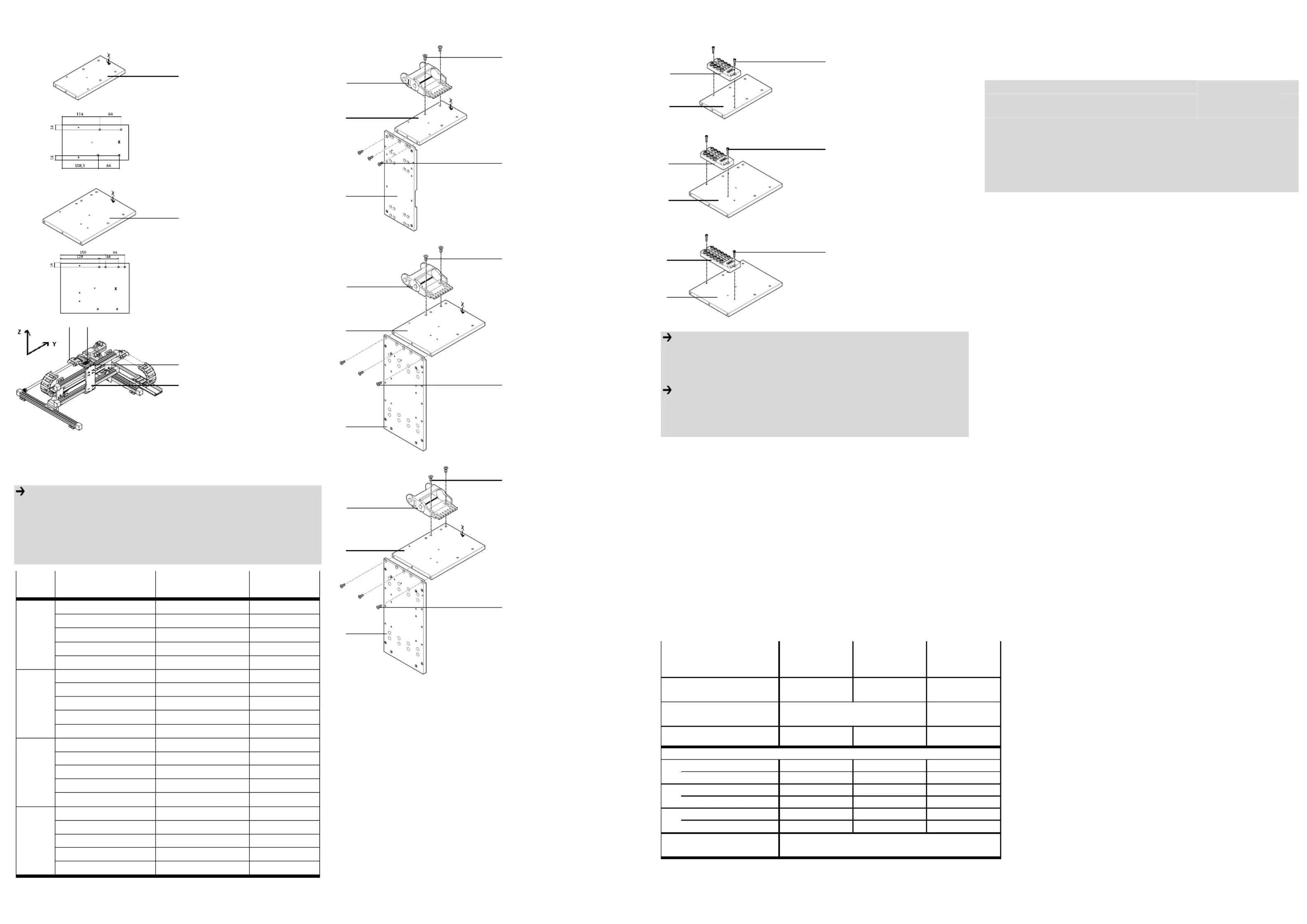
1. Installationsbausätze mit Montagebeispiel
1.a. HMIYF-RF/DL25
1 In
stallationsbausatz
HMIYF-RF/DL25
inklusive Befestigungs-
elemente A-C (siehe Ta-
belle).
1.b. HMIYF-RF/DL40
2 I
n
stallationsbausatz
HMIYF-RF/DL40
inklusive Befestigungs-
elemente A-C (siehe Ta-
belle).
1.c. Monta
gebeispiel
3 Ad
apterbausatz
HMVS-DL-...
4 Multipolverteiler
MPV-E/A..-M8
5 Energieführungskette
Bestimmungsgemäß dient
der Installationsbausatz
HMIYF-RF/DL... 1 bzw. 2
beim Aufbau von Portalsys-
temen als Anbindungsplatte
der E-Kette 5.
Hinweis
• Montieren Sie den Bausatz HMIYF-RF/DL... 1 bzw. 2 je nach Anbin-
dungsvariante. Die Anbindungsvarianten sind von der Ausführungsart
der Antriebsachse bzw. des Portalaufbaus (Mono- oder Duo-Bauweise)
abhängig. Die Zuordnung kann aus Tabelle 1 entnommen werden.
• Verwenden Sie nur zulässige Energieführungsketten laut Katalog.
Art Baukasten Antriebe Anbindungs-
varia
nten
HMBSY-RP.FP-D25-1 DGE-25-SP-KF 2.a.
HMBSY-RP.FP-D25-1 DGE-25-ZR-KF 2.a.
HMBSY-RP.FP-D25-1 DGPL-25-KF 2.a.
HMBSY-RP.FP-D25-2 DGC-25-KF 2.a.
Duo
BG 25
HMBSY-RP.FP-D25-3 DGE-25-ZR-RF
2.a.
HMBSY-RP.FP-M25-1 DGE-25-SP-KF 2.a.
HMBSY-RP.FP-M25-1 DGE-25-ZR-KF 2.a.
HMBSY-RP.FP-M25-1 DGPL-25-KF 2.a.
HMBSY-RP.FP-M25-2 DGC-25-KF 2.a.
Mono
BG 25
HMBSY-RP.FP-M25-3 DGE-25-ZR-RF 2.a.
HMBSY-RP.FP-D40-1 DGE-40-SP-KF 2.b.
HMBSY-RP.FP-D40-1 DGE-40-ZR-KF 2.b.
HMBSY-RP.FP-D40-1 DGE-40-ZR-RF 2.b.
HMBSY-RP.FP-D40-1 DGPL-40-KF 2.b.
Duo
BG 40
HMBSY-RP.FP-D40-2 DGC-40-KF 2.c.
HMBSY-RP.FP-M40-1 DGE-40-SP-KF 2.b.
HMBSY-RP.FP-M40-1 DGE-40-ZR-KF 2.b.
HMBSY-RP.FP-M40-1 DGE-40-ZR-RF 2.b.
HMBSY-RP.FP-M40-1 DGPL-40-KF 2.b.
Mono
BG 40
HMBSY-RP.FP-M40-2 DGC-40-KF 2.c.
Tabelle 1
2. Anbindungsvarianten (siehe Tabelle 1 und 2)
2.a. Duo-Systeme oder Mono-Systeme der Baugröße 25.
1 In
stallationsbausatz
HMIYF-RF/DL25
3 Adapterbausatz
HMVS-DL-25
5 Energieführungskette
•Befestigen Sie den Installa-
tionsbausatz 1 mit der
Seite X nach oben
1)
an der Aussparung am A-
dapterbausatz 3.
•Befestigen Sie die E-Kette
5 an dem Bohrungspaar
wie abgebildet.
2.b. Duo-Systeme oder Mono-Systeme der Baugröße 40 (ohne DGC-40-KF).
2 In
stallationsbausatz
HMIYF-RF/DL40
3 Adapterbausatz
HMVS-DL-40
5 Energieführungskette
•Befestigen Sie den Installa-
tionsbausatz 2 mit der
Seite X nach oben
1)
an der Aussparung am A-
dapterbausatz 3.
•Befestigen Sie die E-Kette
5 an dem Bohrungspaar
wie abgebildet.
2.c. Duo-Systeme oder Mono-Systeme mit DGC-40-KF.
2 In
stallationsbausatz
HMIYF-RF/DL40
3 Adapterbausatz
HMVS-DL-40
5 Energieführungskette
•B
efestigen Sie den Installa-
tionsbausatz 2 mit der
Seite X nach oben
1)
an der Aussparung am A-
dapterbausatz 3.
•Befestigen Sie die E-Kette
5 an dem Bohrungspaar
wie abgebildet.
3. Befestigungsschnittstellen für Anbaukomponenten.
3.a. Befestigungsschnittstelle für MPV-E/A08-M8
1 In
stallationsbausatz
HMIYF-RF/DL25
4 Multipolverteiler
MPV-E/A08-M8
3.b. Befestigungsschnittstelle für MPV-E/A08-M8
2 In
stallationsbausatz
HMIYF-RF/DL40
4 Multipolverteiler
MPV-E/A08-M8
3.c. Befestigungsschnittstelle für MPV-E/A12-M8
2 In
stallationsbausatz
HMIYF-RF/DL40
4 Multipolverteiler
MPV-E/A12-M8
Hinweis
Nach der Montage:
• Verfahren Sie die Achsen von Hand und überprüfen Sie dabei die Instal-
lation bzw. das leichte Abrollen der Energieführungsketten.
Hinweis
• Beachten Sie:
-dass nur Befestigungskombinationen aus der Tabelle zulässig sind.
-zur Erdung, die Montageanleitung des Erdungsbausatzes.
Montageanleitung (de)
688617 / 2005-03NH
†‡
Installationsbausatz
HMIYF-RF/DL...
Festo SE &G Co. K
Postfach
73726 Esslingen
++49/(0)711/347-0
www.festo.com
1
Installationsbausätze
12
12
12
1212
1
1
1
11
bzw.
2
2
2
22
Typ
HMIYF-RF/DL25HMIYF-RF/DL40HMIYF-RF/DL...
Teile-Nr.
539 659539 660
Anbaukomponenten
334
334
334
334334
Typ
HMVS-DL25HMVS-DL40MPV-E/A..-M8
Anbaukomponente
Typ
Anbindungsvariante /
Schnittstelle
2.a.2.b. /c.3.a. / b. / c.
Senkschrauben
M5x14 DIN 79913x3x
Senkschrauben
M6x16 DIN 79912x2x
Zylinderschrauben
M4x18 DIN 9122x
M4M5M6
2,95,810
5
5
5
55
1) Bei Anbindung der Energieführungskette
5
aus entgegengesetzter
Richtung als abgebildet, wenden Sie die Platte des Installations-
bausatzes
1
bzw.
2
entsprechend.
Gewinde
Befestigungselemente im Lieferumfang der Bausätze
Tabelle 2
Anzugsdrehmomente in Nm
A
C
E-Kette
B
2
1
-
2
3
5
5
1
3
B
A
5
2
3
B
A
4
1
C
C
4
2
4
2
C
5
2
3
B
A
4
Product specificaties
| Merk: | Festo |
| Categorie: | Niet gecategoriseerd |
| Model: | HMIYF-RF/DL40 |
Heb je hulp nodig?
Als je hulp nodig hebt met Festo HMIYF-RF/DL40 stel dan hieronder een vraag en andere gebruikers zullen je antwoorden
Handleiding Niet gecategoriseerd Festo

3 Mei 2026
30 April 2026
29 April 2026
29 April 2026
29 April 2026
29 April 2026
28 April 2026
28 April 2026
28 April 2026
28 April 2026
Handleiding Niet gecategoriseerd
Nieuwste handleidingen voor Niet gecategoriseerd
23 Juli 2026
23 Juli 2026
23 Juli 2026
23 Juli 2026
23 Juli 2026
23 Juli 2026
22 Juli 2026
22 Juli 2026
22 Juli 2026
22 Juli 2026