Festo HMIY-RP/FP-E07 Handleiding
Festo Niet gecategoriseerd HMIY-RP/FP-E07
Bekijk gratis de handleiding van Festo HMIY-RP/FP-E07 (2 pagina’s), behorend tot de categorie Niet gecategoriseerd. Deze gids werd als nuttig beoordeeld door 27 mensen en kreeg gemiddeld 5.0 sterren uit 8 reviews. Heb je een vraag over Festo HMIY-RP/FP-E07 of wil je andere gebruikers van dit product iets vragen? Stel een vraag
Pagina 1/2
Montageanleitung (de)
744 380 / 2009-09NH
†‡
Installationsbausatz
HMIY-RP/FP-E07
Festo SE &G Co. K
Postfach
D-73726 Esslingen
++49/(0)711/347-0
www.festo.com
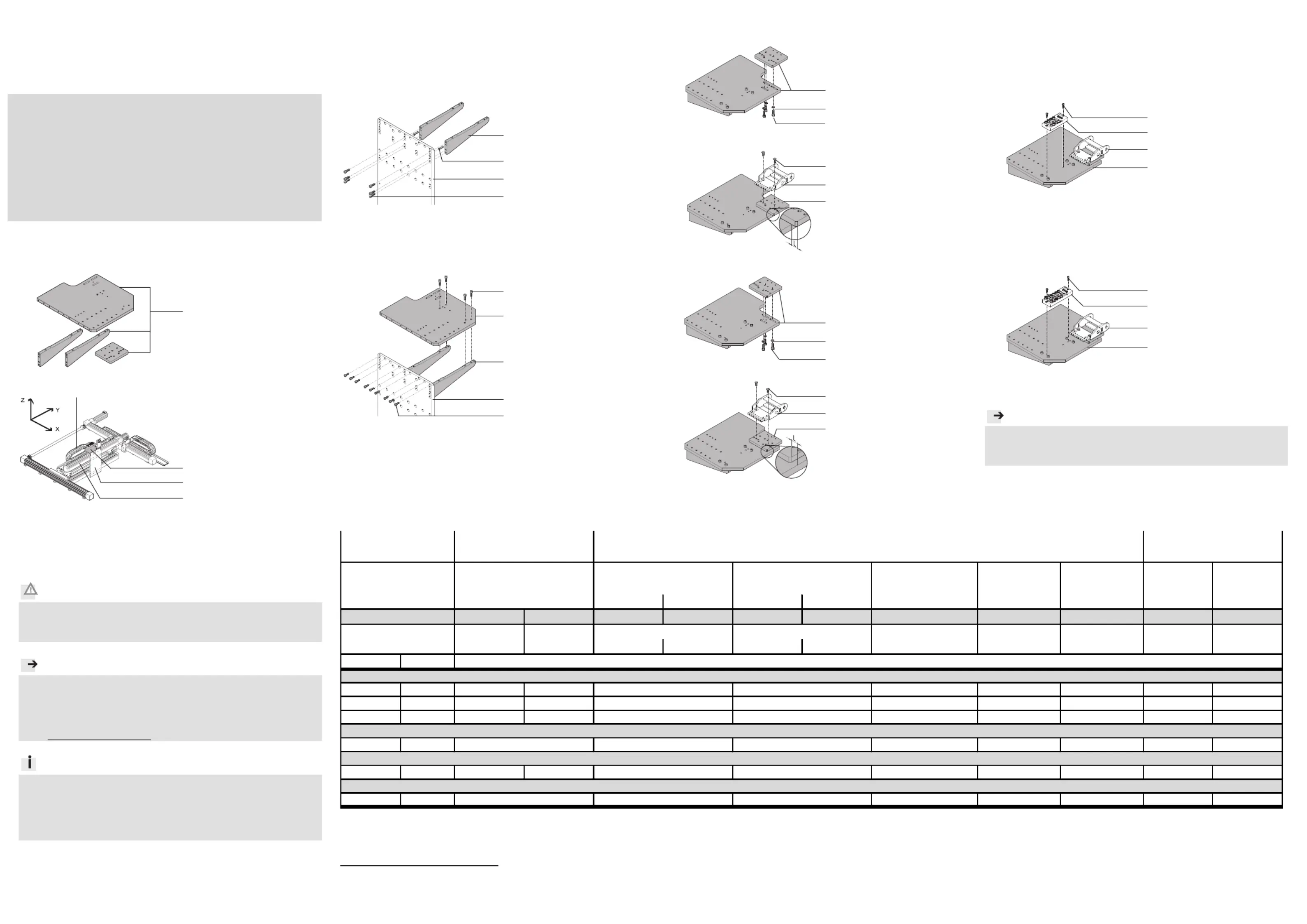
1.Installationsbausatz
1a.HMIY-RP/FP-E07
13912d_2
1Installationsbausatz
HMIY-RP/FP-E07
1b.Montagebeispiel
13912d_1
2Adapterbausatz
HMVS-DL63
3Antriebseinheit
(! Tabelle)
4Energieführungskette
E07
Bestimmungsgemäß dient der
Installationsbausatz
HMIY-RP/FP-E07 1 zur Befesti-
gung der E-Kette 4 beim Auf-
bau von Portalsystemen in
Duo-Bauweise.
Vorsicht
Verletzungsgefahr durch elektrische Spannung.
•Verbinden Sie den Bausatz 1 mit dem Schutzleitersystem
! Montageanleitung Erdungsbausatz für HM…63… (HMVS-DL63).
Hinweis
•Beachten Sie, dass nur Befestigungskombinationen aus der Tabelle zu-
lässig sind.
•Halten Sie die zulässigen Anziehdrehmomente ein (! Tabelle).
•Verwenden Sie nur zulässige E-Ketten 4 laut Katalog
!www.festo.com/catalogue.
Info
•Beachten Sie die Montagereihenfolge
! Montageübersicht für HM…63… (HMVS-DL63).
Der Bausatz 1 enthält alle maximal erforderlichen Befestigungselemente.
•Beachten Sie, dass bei einigen Kombinationen Befestigungselemente
übrig bleiben.
2.Montage Installationsbausatz 1
1
1
11
•Wählen Sie die Befestigungselemente (Schrauben, usw.) für Ihre Kombina-
tion (! Tabelle).
•Beachten Sie die Bildzuordnung für Ihre Kombination (! Tabelle).
Bild 1a
13912d_2
1Installationsbausatz
HMIY-RP/FP-E07
2Adapterbausatz
HMVS-DL63
Bild 1b
13912d_3
1Installationsbausatz
HMIY-RP/FP-E07
2Adapterbausatz
HMVS-DL63
1)2
1)
Toleranzen für nicht tolerierte Anziehdrehmomente M
A
M
A
> 1 Nm: ± 20%
2)
Die Antriebseinheit 3 ist keine direkte Anbaukomponente für den Bausatz 1.
Bild 2
13912d_5
1Installationsbausatz
HMIY-RP/FP-E07
3Antriebseinheit
DGPL-63-…-KF
DGC-63-…-KF
DGE-63-…-SP-KF
DGE-63-…-ZR-KF
13912d_6
1Installationsbausatz
HMIY-RP/FP-E07
4E-Kette
E07
•Halten Sie das Maß L abhän-
gig von Ihrer Antriebsein-
heit 3 ein (!Tabelle).
Bild 3
13912d_8
1Installationsbausatz
HMIY-RP/FP-E07
3Antriebseinheit
DGPL-50-…-KF
DGC-50-…-KF
DGE-63-…-ZR-RF
13912d_9
1Installationsbausatz
HMIY-RP/FP-E07
4E-Kette
E07
•Halten Sie das Maß L abhän-
gig von Ihrer Antriebsein-
heit 3 ein (!Tabelle).
3.M
ontage Anbaukomponenten 5
5
5
55 – 6
6
6
66
•W
ählen Sie die Befestigungselemente (Schrauben, usw.) für Ihre Kombina-
tion (! Tabelle).
•Beachten Sie die Bildzuordnung für Ihre Kombination (! Tabelle).
Bild 4
13912d_10
1Installationsbausatz
HMIY-RP/FP-E07
5Multipolverteiler
MPV-E/A08-M8
4E-Kette
E07
Bil
d 5
13912d_11
1Installationsbausatz
HMIY-RP/FP-E07
5Multipolverteiler
MPV-E/A12-M8
4E-Kette
E07
Hinweis
Nach der Montage:
•Verfahren Sie die Achsen von Hand und überprüfen Sie dabei die In-
stallation bzw. das leichte Abrollen der Energieführungsketten.
255
50635063636363
1a1b323222345
E-Kette
4
Maß L [mm]17,54,513,517,5
M
A
1)
[Nm]
M4x1632x2x
M5x1669x
M6x20106x4x3x3x3x3x3x
M6x1662x2x2x2x2x
6m6x242x
B6,43x3x3x3x3x
MPV-E/A08-M8MPV-E/A12-M8
–– ––
C Zylinderstift nach DIN 7
1
HMIY-RP/FP-E07
Bild
––
E07
HMVS-DL63
1
HMIY-RP/FP-E07
DGE-...-...-SP-KF-
2)
E07
3
DGPL-...-...-KF-
2)
Bausatz
3
DGE-...-...-ZR-RF-
2)
DGC-...-...-KF-
2)
DGE-...-...-ZR-KF-
2)
4,5
3
Anbaukomponente/
Antriebseinheit Y-Achse
2)
B Senkschraube nach DIN 7991
––
E07E07E07
33
1
HMIY-RP/FP-E07
D Scheibe nach DIN 125
4,5
A Zylinderschraube nach DIN 912
9
1
2
1
C
1
1
A
A
1
A
D
4
1
B
1
1
4
B
5
1
2
4
3
1
4
A
A
5
4
1
A
2
D
A
3289d_5
Raumportal
Product specificaties
| Merk: | Festo |
| Categorie: | Niet gecategoriseerd |
| Model: | HMIY-RP/FP-E07 |
Heb je hulp nodig?
Als je hulp nodig hebt met Festo HMIY-RP/FP-E07 stel dan hieronder een vraag en andere gebruikers zullen je antwoorden
Handleiding Niet gecategoriseerd Festo

3 Mei 2026
30 April 2026
29 April 2026
29 April 2026
29 April 2026
29 April 2026
28 April 2026
28 April 2026
28 April 2026
28 April 2026
Handleiding Niet gecategoriseerd
Nieuwste handleidingen voor Niet gecategoriseerd
23 Juli 2026
23 Juli 2026
23 Juli 2026
23 Juli 2026
23 Juli 2026
23 Juli 2026
22 Juli 2026
22 Juli 2026
22 Juli 2026
22 Juli 2026