Festo HMIXB-RP/FP-2 Handleiding
Festo Niet gecategoriseerd HMIXB-RP/FP-2
Bekijk gratis de handleiding van Festo HMIXB-RP/FP-2 (438 pagina’s), behorend tot de categorie Niet gecategoriseerd. Deze gids werd als nuttig beoordeeld door 4 mensen en kreeg gemiddeld 4.6 sterren uit 8 reviews. Heb je een vraag over Festo HMIXB-RP/FP-2 of wil je andere gebruikers van dit product iets vragen? Stel een vraag
Pagina 1/438
Montageanleitung (de)
744 386 / 2009-09NH
†‡
Installationsbausatz
HMIXB-RP/FP-2
Festo SE & Co. KG
Postfach
D-73726 Esslingen
++49/(0)711/347-0
www.festo.com
1.Installationsbausatz
1a.HMIXB-RP/FP-2
13916d_2
1Installationsbausatz
HMIXB-RP/FP-2
1b.Montagebeispiel
13916d_1..Raumportal
2Antriebseinheit
(! Tabelle)
3Anbaukomponente
(! Tabelle)
Bestimmungsgemäß dient der Installationsbausatz HMIXB-RP/FP-2 1 als
Basis zum Aufbau von Raumportalsystemen in Duo-Bauweise (X-Module).
Vorsicht
Verletzungsgefahr durch elektrische Spannung.
•Verbinden Sie den Bausatz 1 mit dem Schutzleitersystem
! Montageanleitung Erdungsbausatz für HM…63… (HMVS-DL63).
Hinweis
•Befestigen Sie eine Mittenstütze 3 mindestens alle 500 mm.
•Befestigen Sie einen Bausatz 1 mindestens alle 1000 mm.
Berechnen Sie die dazu benötigte Anzahl y nach folgenden Formeln:
–bei Hub ≤ 1000 mm: y = 2
–bei Hub > 1000 mm: y = Ganzzahl (Hub/1000) +2
•Montieren Sie die Antriebe 2 immer zuerst an den Bausatz 1.
•Verwenden Sie nur zulässige Energieführungsketten 3 laut Katalog
www.festo.com/catalogue.
•Beachten Sie, dass nur Befestigungskombinationen aus der Tabelle
zulässig sind.
•Halten Sie die zulässigen Anziehdrehmomente ein (! Tabelle).
Info
•Beachten Sie die Montagereihenfolge
! Montageübersicht für HM…63… (HMVS-DL63).
Der Bausatz 1 enthält alle maximal erforderlichen
Befestigungselemente.
•Beachten Sie, dass bei einigen Kombinationen Befestigungselemente
übrig bleiben.
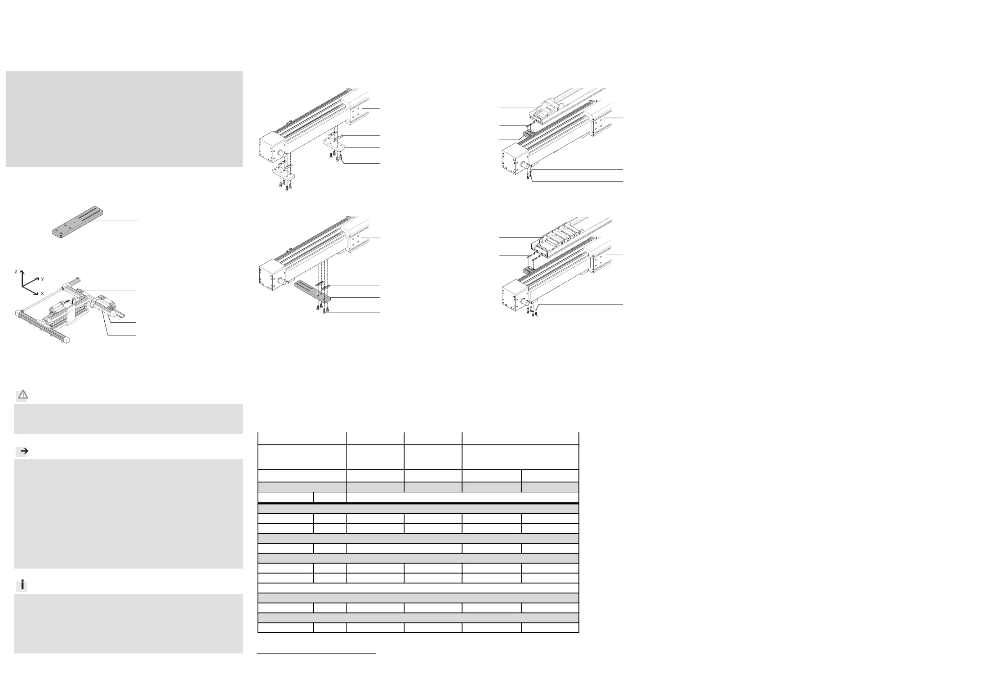
2.Montage an Antriebseinheit 2
2
2
22
•Wählen Sie die Befestigungselemente (Sch
rauben, usw.) für Ihre
Kombination (! Tabelle).
•Beachten Sie die Bildzuordnung für Ihre Kombination (! Tabelle).
Bild 1
13916d_3
2Linearantrieb
DGE-63-…-ZR-KF
3Mittenstütze
MUP-63
•Befestigen Sie eine
Mittenstütze 3 mindestens
alle 500 mm.
Bild 2
13916d_4
1Installationsbausatz
HMIXB-RP/FP-2
2Linearantrieb
DGE-63-…-ZR-KF
•Befestigen Sie einen
Bausatz 1 mindestens
alle 1000 mm.
1)
2
1)
Toleranzen für nicht tolerierte Anziehdrehmomente M
A
M
A
> 1 Nm: ± 20%
2)
wahlweise
3.Montage an Anbaukomponente 3
3
3
33
•Wählen Sie die Befestigungselemente (Sch
rauben, usw.) für Ihre
Kombination (! Tabelle).
•Beachten Sie die Bildzuordnung für Ihre Kombination (! Tabelle).
Bild 3
Bild 3a
13916d_5
1Installationsbausatz
HMIXB-RP/FP-2
2Linearantrieb
DGE-63-…-ZR-KF
3Auflageprofil
HMIA-E05/-E07
2)
Bild 3b
13916d_5
1Installationsbausatz
HMIXB-RP/FP-2
2Linearantrieb
DGE-63-…-ZR-KF
3Auflageprofil
HMIA-E10
Raumportal
3289d_5
1
1
2
3
B
2
HMIXB-RP/FP-2
DGE-...-ZR-KFDGE-...-ZR-KF
6363
MUP-63HMIA-E05/-E07
2)
HMIA-E10
123a3b
M
A
1)
[Nm]
M5x1062x4x
M8x16244x
B5,32x4x
MUP- 32/401x2x
NST-HMV-8-2-M82x
M8x18244x
NST-HMV-8-2-M82x
1
Bausatz
DGE-...-ZR-KF
HMIXB-RP/FP-2
Bild
D Zylinderschraube nach DIN 912
63
Befestigungselemente im Lieferumfang der Anbaukomponenten
A Zylinderschraube nach DIN 912
B Scheibe nach DIN 125
E Nutenstein
2
Antriebseinheit
3
Anbaukomponente
C Nutenstein
2
E
3
A
B
C
1
C
3
1
A
A
2
C
D
3
1
2
Product specificaties
| Merk: | Festo |
| Categorie: | Niet gecategoriseerd |
| Model: | HMIXB-RP/FP-2 |
Heb je hulp nodig?
Als je hulp nodig hebt met Festo HMIXB-RP/FP-2 stel dan hieronder een vraag en andere gebruikers zullen je antwoorden
Handleiding Niet gecategoriseerd Festo

3 Mei 2026
30 April 2026
29 April 2026
29 April 2026
29 April 2026
29 April 2026
28 April 2026
28 April 2026
28 April 2026
28 April 2026
Handleiding Niet gecategoriseerd
Nieuwste handleidingen voor Niet gecategoriseerd
23 Juli 2026
23 Juli 2026
23 Juli 2026
23 Juli 2026
23 Juli 2026
23 Juli 2026
22 Juli 2026
22 Juli 2026
22 Juli 2026
22 Juli 2026