Festo HMIX-RP/FP-E07/E10 Handleiding
Festo Niet gecategoriseerd HMIX-RP/FP-E07/E10
Bekijk gratis de handleiding van Festo HMIX-RP/FP-E07/E10 (2 pagina’s), behorend tot de categorie Niet gecategoriseerd. Deze gids werd als nuttig beoordeeld door 20 mensen en kreeg gemiddeld 4.4 sterren uit 8 reviews. Heb je een vraag over Festo HMIX-RP/FP-E07/E10 of wil je andere gebruikers van dit product iets vragen? Stel een vraag
Pagina 1/2
Montageanleitung (de)
744 385 / 2010-10NH
†‡
Installationsbausatz
HMIX-RP/FP-E07/E10
Festo SE& Co. KG
Postfach
D-73726 Esslingen
++49/(0)711/347-0
www.festo.com
1.Teileliste
15757d_2
1 Installationsbausatz
HMIX-RP/FP-E07/E10
(A)
Zylinderschraube (15x)
(B)Zylinderstift (3x)
(C)
Senkschraube (2x)
(D)Unterlegscheibe (3x)
Bestimmungsgemäß dient der
Installationsbausatz
HMIX-RP/FP-E07/E10 1 zur Be-
festigung der Energieführungs-
kette (E-Kette) 4 beim Aufbau
von Portalsystemen in
Duo-Bauweise.
15757d_1
2 Befestigungswinkel
HMVW-DL63-2
3 Antriebseinheit
X-Achse ( Tabelle)
4 E-Kette
E07/E10
5 Auflageprofil
Vorsicht
Verletzungsgefahr durch elektrische Spannung.
•Verbinden Sie den Bausatz 1 mit dem Schutzleitersystem
Montageanleitung Erdungsbausatz (beiliegend in HMVS-DL63).
Hinweis
•Beachten Sie, dass nur Befestigungskombinationen aus der Tabelle zu-
lässig sind.
•Halten Sie die zulässigen Anziehdrehmomente ein ( Tabelle).
•Verwenden Sie nur zulässige E-Ketten 4 laut Katalog
www.festo.com/catalogue.
Info
•Beachten Sie die Montagereihenfolge
Montageübersicht (beiliegend in HMVS-DL63).
Der Bausatz 1 enthält alle maximal erforderlichen Befestigungselemente.
•Beachten Sie, dass bei einigen Kombinationen Befestigungselemente
übrig bleiben.
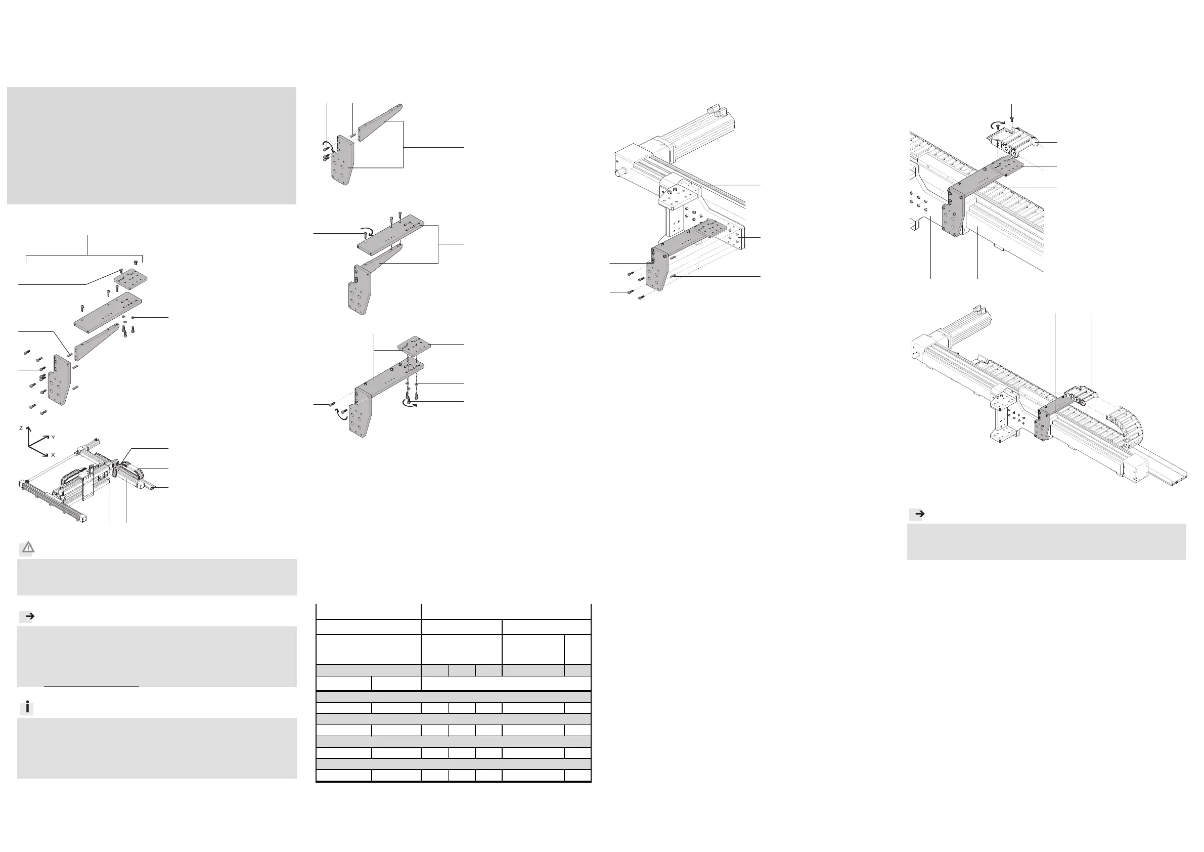
2.Vormontage Installationsbausatz 1
•Wählen Sie die Befestigungselemente (Schrauben usw.) für Ihre Kombina-
tion ( Tabelle).
•Beachten Sie die Bildzuordnung für Ihre Kombination ( Tabelle).
Bild 1
Bild 1a
15757d_3
1 Installationsbausatz
HMIX-RP/FP-E07/E10
Bild 1b
15757d_4
1 Installationsbausatz
HMIX-RP/FP-E07/E10
Bild 1c
15757d_5
1 Installationsbausatz
HMIX-RP/FP-E07/E10
Die genaue Position der Plat-
te (E) ist von der Position des
Auflageprofils 5 und der
E-Kette 4 abhängig.
•Befestigen Sie die Platte (E)
des Bausatzes 1 zunächst
nur lose.
1)2
1)
Toleranzen für nicht tolerierte Anziehdrehmomente M
A
± 20%
2)
wahlweise
3.Montage Installationsbausatz 1
•Wählen Sie die Befestigungselemente (Schrauben usw.) für Ihre Kombina-
tion ( Tabelle).
•Beachten Sie die Bildzuordnung für Ihre Kombination ( Tabelle).
Bild 2
15757d_6
1 Installationsbausatz
HMIX-RP/FP-E07/E10
2 Befestigungswinkel
HMVW-DL63-2
3 Antriebseinheit
DGE-63-…-ZR-KF-
4.Montage Anbaukomponenten 4
•Wählen
Sie di
e Befestigungselemente (Schrauben, usw.) für Ihre Kombina-
tion ( Tabelle).
•Beachten Sie die Bildzuordnung für Ihre Kombination ( Tabelle).
Bild 3
Bild 3a
15757d_7
Bild 3b
1 Instal
latio
nsbausatz
HMIX-RP/FP-E07/E10
2 Befestigungswinkel
HMVW-DL63-2
3 Antriebseinheit
DGE-63-…-ZR-KF-
4 E-Kette
E07/E10
•Richten Sie die Platte (E) mit
der E-Kette 4 nun aus und
befestigen Sie sie anschlie-
ßend Bild 1c.
15757d_8
Hinweis
Nach der Montage:
•Verfahren Sie die Achsen von Hand und überprüfen Sie dabei die In-
stallation bzw. das leichte Abrollen der E-Ketten.
HMVW-DL63-2E07
2)
E10
2)
1a1b1c23
M
A
1)
[Nm]
M6x20103x3x5x4x
6m6x241x2x
M6x1662x
B6,43x
D Scheibe nach DIN 125
A Zylinderschraube nach DIN 912
HMIX-RP/FP-E07/E10
B Zylinderstift nach DIN 7
2
/
4
Anbaukomponente
Bild
1
Bausatz
3
Antriebseinheit
C Senkschraube nach DIN 7991
DGE-63-…-ZR-KF
1
3
2
Raumportal
4
1
A B
A
B
1
A
1
A
D
D
1
C
1
2
3
A
B
1
3
4
2
C
E
E
3289d_5
4
1
5
A
Product specificaties
| Merk: | Festo |
| Categorie: | Niet gecategoriseerd |
| Model: | HMIX-RP/FP-E07/E10 |
Heb je hulp nodig?
Als je hulp nodig hebt met Festo HMIX-RP/FP-E07/E10 stel dan hieronder een vraag en andere gebruikers zullen je antwoorden
Handleiding Niet gecategoriseerd Festo

3 Mei 2026
30 April 2026
29 April 2026
29 April 2026
29 April 2026
29 April 2026
28 April 2026
28 April 2026
28 April 2026
28 April 2026
Handleiding Niet gecategoriseerd
Nieuwste handleidingen voor Niet gecategoriseerd
23 Juli 2026
23 Juli 2026
23 Juli 2026
23 Juli 2026
23 Juli 2026
23 Juli 2026
22 Juli 2026
22 Juli 2026
22 Juli 2026
22 Juli 2026