Festo HMIW-E05/E07 Handleiding
Festo Niet gecategoriseerd HMIW-E05/E07
Bekijk gratis de handleiding van Festo HMIW-E05/E07 (2 pagina’s), behorend tot de categorie Niet gecategoriseerd. Deze gids werd als nuttig beoordeeld door 14 mensen en kreeg gemiddeld 4.2 sterren uit 2 reviews. Heb je een vraag over Festo HMIW-E05/E07 of wil je andere gebruikers van dit product iets vragen? Stel een vraag
Pagina 1/2
Montageanleitung (de)
744 382 / 2010-03NH
†‡
Installationsbausatz
HMIW-E05/E07
Festo SE &G Co. K
Postfach
D-73726 Esslingen
++49/(0)711/347-0
www.festo.com
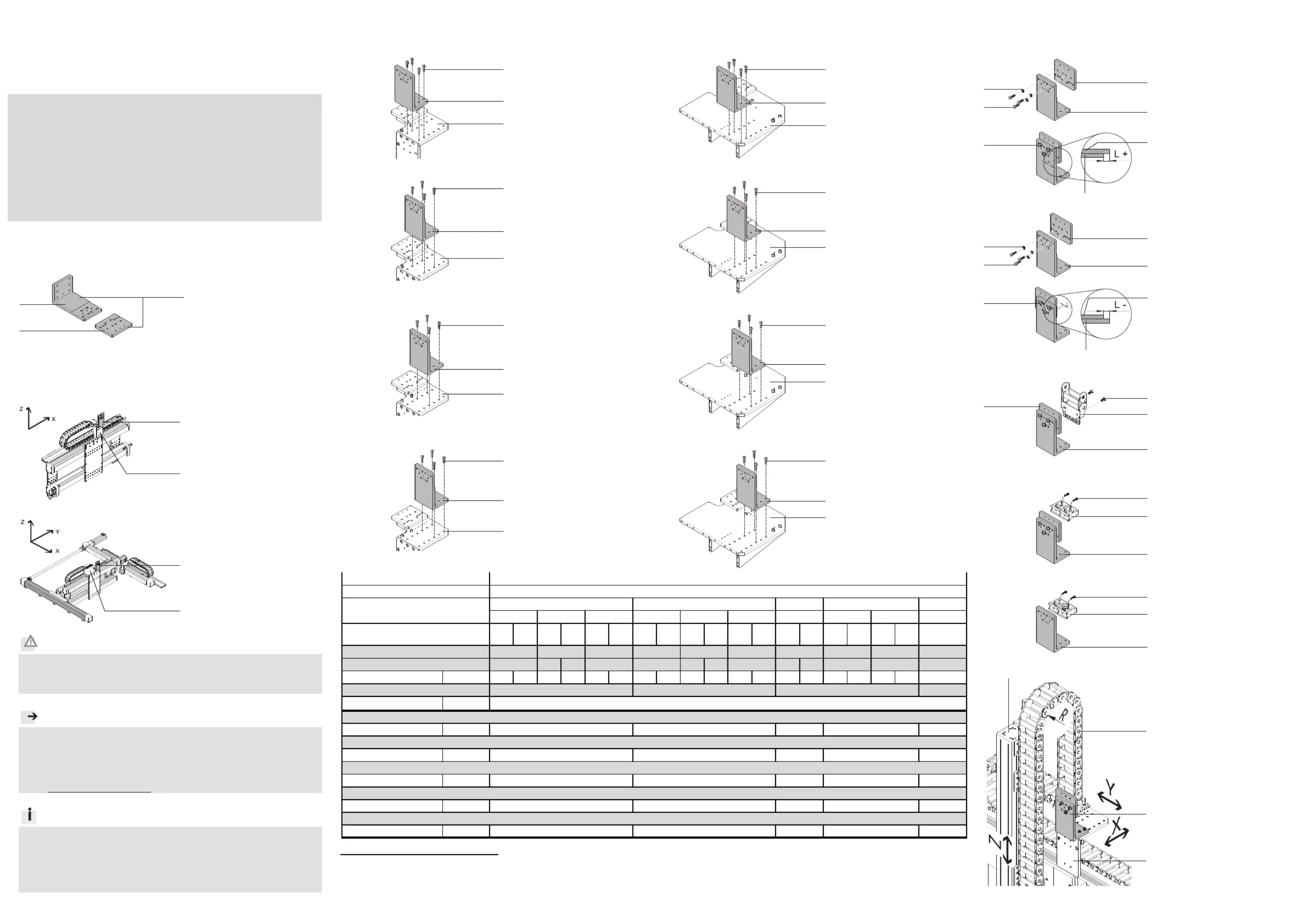
1.Installationsbausatz
1a.HMIW-E05/E07
14618d_3
1Installationsbausatz
HMIW-E05/E07
(A)
Winkel
(B
)Platte
Bestimmungsgemäß dient der Installationsbausatz 1 daz
u, beim Aufbau von
Portalsystemen die Energieführungskette/Klemmschelle 4 zu befestigen.
2.Montagebeispiel
14618d_1
2Installationsbausatz
HMIY-LP-E07
Bild 1
14618d_2
2Installationsbausatz
HMIY-RP/FP-E07
Bild 2
Vorsicht
Verletzungsgefahr durch elektrische Spannung.
Verbinden Sie den Bausatz 1 mit dem Schutzleitersystem
Montageanleitung Erdungsbausatz für HM…63… (HMVS-DL63).
Hinweis
Beachten Sie, dass nur Befestigungskombinationen aus der Tabelle zu-
lässig sind.
Halten Sie die zulässigen Anziehdrehmomente ein ( Tabelle).
Verwenden Sie nur zulässige E-Ketten 4 laut Katalog
www.festo.com/catalogue.
Info
Beachten Sie die Montagereihenfolge
Montageübersicht für HM...63... (HMVS-DL63).
Wählen Sie die Befestigungselemente (Schrauben, usw.) für Ihre Kombi-
nation ( Tabelle).
Beachten Sie die Bildzuordnung für Ihre Kombination ( Tabelle).
Bild 3
3.Montage Winkel (A) an Linienportal
Bild 3a
14618d_6
1Installationsbausatz
HMIW-E05/E07
2Installationsbausatz
HMIY-LP-E07
3Antriebseinheit
DGEA-40
( Tabelle)
Bild 3b
14618d_7
1Installationsbausatz
HMIW-E05/E07
2Installationsbausatz
HMIY-LP-E07
3Antriebseinheit
DG...-63
( Tabelle)
Bild 3c
14618d_8
1Installationsbausatz
HMIW-E05/E07
2Installationsbausatz
HMIY-LP-E07
3Antriebseinheit
DG...-50
( Tabelle)
Bild 3d
14618d_9
1Installationsbausatz
HMIW-E05/E07
2Installationsbausatz
HMIY-LP-E07
3Antriebseinheit
DG...-40
( Tabelle)
1)2)3)
1)
Die Z-Achse 3 ist keine direkte Anbaukomponente für diesen Bausatz.
2)
wahlweise
3)
Toleranzen für nicht tolerierte Anziehdrehmomente M
A
M
A
> 1 Nm: ± 20%
4.Montage Winkel (A) an Raumportal
Bild 3e
14618d_10
1Installationsbausatz
HMIW-E05/E07
2Installationsbausatz
HMIY-RP/FP-E07
3Antriebseinheit
DGEA-40
( Tabelle)
Bild 3f
14618d_11
1Installationsbausatz
HMIW-E05/E07
2Installationsbausatz
HMIY-RP/FP-E07
3Antriebseinheit
DG...-63
( Tabelle)
Bild 3g
14618d_12
1Installationsbausatz
HMIW-E05/E07
2Installationsbausatz
HMIY-RP/FP-E07
3Antriebseinheit
DG...-50
( Tabelle)
Bild 3h
14618d_13
1Installationsbausatz
HMIW-E05/E07
2Installationsbausatz
HMIY-RP/FP-E07
3Antriebseinheit
DG...-40
( Tabelle)
Bild 4
5.Montage Platte (B)
Bild 4aMaß L (+)
14618d_14
1Installationsbausatz
HMIW-E05/E07
14618d_15
Beachten Sie das Maß L
( Tabelle).
Bild 4bMaß L (–
)
14618d_16
1Installationsbausatz
HMIW-E05/E07.
14618d_17
Beachten Sie das Maß L
( Tabelle).
Bild 5
6.M
ontage Anbaukomponente 4
4
4
44
Bil
d 5a
14618d_18
1Installationsbausatz
HMIW-E05/E07
4Energieführungskette
E05/E07
Montieren Sie die E-Kette 4
mittig auf die Platte (B) des
Installationsbausatzes 1.
Bild 5b
14618d_19
1Installationsbausatz
HMIW-E05/E07
4Klemmschelle
MKRS-
Bild 5c
14618d_20
1Installationsbausatz
HMIW-E05/E07
4Klemmschelle
MKRS-
7.Endmont
age am Beispiel Linienportal
14618d_4
Prüfen Sie, ob der Installati-
onsbausatz 1 an die richti-
gen Stellen montiert wurde
(abhängig von Ihrer Kombina-
tion). Denn nur dann ist der
erforderliche Biegeradius R >
50 mm, jedoch nicht wesent-
lich größer.
Richten Sie die E-Kette 4 mit
dem Installationsbausatz 1
in X- und Y-Richtung aus.
Nach der Montage:
Verfahren Sie die Achsen von
Hand und überprüfen Sie die
Installation bzw. das leichte
Abrollen der E-Ketten.
3
918d_7
Linienportal
2
1
E05E07E05E07E05E07E05E07E05E07E05E07E05E07E05E07E05E07
5b5a5b5a5b5a
Maß L
-15-5-37515-12-2-42212-82-16-6515
M
A
3)
[Nm]
M6x2010
M6x2010
B6,4
M6x166
M4x163
HMP-
32
2)
4x
2x
3x
3x
6a
1
Bausatz
2
Bausatz
Bild 3. / 4.
2)
3x
3x
Bild 6.
3
Antriebseinheit Z-Achse
1)
DGPL-...-KF-
50
6a
40
Bild 5.
3d / 4d3c / 4c3b / 4b
5a5b
3x
3x
2x
5063
3d / 4d3c / 4c3b / 4b
4x
6340
3d / 4d3b / 4b
5b
2x
5b5a
6a
DGEA-
40
3x
3x
HMIW-E05/E07
HMIY-LP-E07 / HMIY-RP/FP-E07
4x
3x
3x
DGC-...-KF-
4
E-Kette / Klemmschelle
MKRS-
23/29-B
G Zylinderschraube nach DIN 912
F Senkschraube nach DIN 7991
E Scheibe nach DIN 125
DGE-...-SP-KF-
4063
C Zylinderschraube nach DIN 912
3a / 4a
D Zylinderschraube nach DIN 912
2x
4x
2x
6b / 6c
2)
5a
2)
4x
2
1
B
A
1
C
2
1
C
2
1
C
2
1
C
2
1
C
2
1
C
2
1
C
2
1
C
A
B
D
E
D
A
B
D
E
1
2
4
3
1
4
F
1
4
G
1
4
G
A
B
D
A
B
B
1
2
Raumportal
3289d_5
Product specificaties
| Merk: | Festo |
| Categorie: | Niet gecategoriseerd |
| Model: | HMIW-E05/E07 |
Heb je hulp nodig?
Als je hulp nodig hebt met Festo HMIW-E05/E07 stel dan hieronder een vraag en andere gebruikers zullen je antwoorden
Handleiding Niet gecategoriseerd Festo

3 Mei 2026
30 April 2026
29 April 2026
29 April 2026
29 April 2026
29 April 2026
28 April 2026
28 April 2026
28 April 2026
28 April 2026
Handleiding Niet gecategoriseerd
Nieuwste handleidingen voor Niet gecategoriseerd
23 Juli 2026
23 Juli 2026
23 Juli 2026
23 Juli 2026
23 Juli 2026
22 Juli 2026
22 Juli 2026
22 Juli 2026
22 Juli 2026
22 Juli 2026