Festo EAPM-G1-35-SLS Handleiding
Festo Niet gecategoriseerd EAPM-G1-35-SLS
Bekijk gratis de handleiding van Festo EAPM-G1-35-SLS (2 pagina’s), behorend tot de categorie Niet gecategoriseerd. Deze gids werd als nuttig beoordeeld door 16 mensen en kreeg gemiddeld 4.7 sterren uit 5 reviews. Heb je een vraag over Festo EAPM-G1-35-SLS of wil je andere gebruikers van dit product iets vragen? Stel een vraag
Pagina 1/2
Montageanleitung (de)
749 979 / 2010-02NH
†‡
Schaltfahne
EAPM-G1-...-SLS
Festo SE &G Co. K
Postfach
D-73726 Esslingen
++49/(0)711/347-0
www.festo.com
1.Teileliste
14519d_1
1Schaltfahne (1x)
EAPM-G1-...-SLS
2Zylinderschraube (2x)
( Tabelle)
Bestimmungsgemäß dient die Schaltfahne 1 daz
u, die
Näherungs-
schalter (C) die in den Sensornuten der Achse befestigt sind zu schalten.
2.Schraubengrößen und Anziehdrehmomente M
A
1)
EAPM-G1- 35-S
LS 45-SLS55-SLS75-SLS
2Schraube M4x6 M5x8 M5x8 M6x10
M
A
[Nm] 2,95,95,99,9
1)
Toleranzen für nicht tolerierte Anziehdrehmomente M
A
M
A
> 1Nm: ± 20%
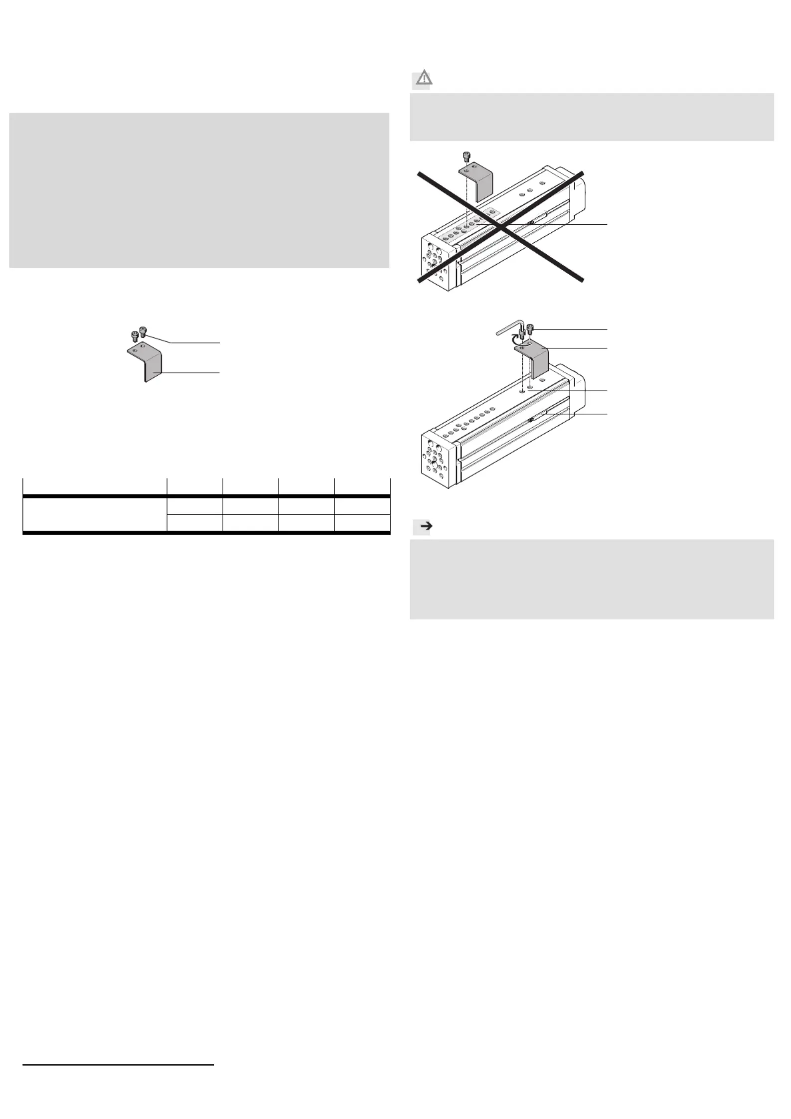
3.Montage
Vorsicht
Quetsch- und Abschergefahr durch Falschmontage.
Verletzung der Finger!
Montieren Sie die Schaltfahne 1 wie folgt:
14519d_3
Stellen Sie sicher, dass die
Schaltfahne 1 nicht im vor-
deren Bereich (A) der Füh-
rung montiert wird.
14519d_2
Platzieren Sie die Schalt-
fahne 1 nach rechts oder
links an den Befestigungs-
bohrungen (B).
Drehen Sie die Schrau-
ben 2fest. Halten Sie das
zulässige Anziehdreh-
moment ein.
Hinweis
Es verbleibt ein Abstand S = 0,5 … 2 mm zwischen dem Näherungs-
schalter (C) und der Schaltfahne 1.
Vermeiden Sie eine Fremdbeeinflussung im Nahbereich der Näherungs-
schalter, durch andere magnetische oder ferritische Teile als die Schalt-
fahne 1.
C
1
A
2
1
B
2
Product specificaties
| Merk: | Festo |
| Categorie: | Niet gecategoriseerd |
| Model: | EAPM-G1-35-SLS |
Heb je hulp nodig?
Als je hulp nodig hebt met Festo EAPM-G1-35-SLS stel dan hieronder een vraag en andere gebruikers zullen je antwoorden
Handleiding Niet gecategoriseerd Festo

3 Mei 2026
30 April 2026
29 April 2026
29 April 2026
29 April 2026
29 April 2026
28 April 2026
28 April 2026
28 April 2026
28 April 2026
Handleiding Niet gecategoriseerd
Nieuwste handleidingen voor Niet gecategoriseerd
23 Juli 2026
23 Juli 2026
23 Juli 2026
23 Juli 2026
23 Juli 2026
23 Juli 2026
23 Juli 2026
23 Juli 2026
23 Juli 2026
22 Juli 2026