Festo CPX-FB39 Handleiding
Festo Niet gecategoriseerd CPX-FB39
Bekijk gratis de handleiding van Festo CPX-FB39 (2 pagina’s), behorend tot de categorie Niet gecategoriseerd. Deze gids werd als nuttig beoordeeld door 2 mensen en kreeg gemiddeld 4.8 sterren uit 4 reviews. Heb je een vraag over Festo CPX-FB39 of wil je andere gebruikers van dit product iets vragen? Stel een vraag
Pagina 1/2
Bus node
CPX-FB39
Festo SE & Co. KG
Ruiter Straße 82
73734 Esslingen
Germany
+49 711 347-0
www.festo.com
Brief description
Translation of the original instructions
8101652
2018-11a
[8101654]
Bus node CPX-FB39English............................................
For all available product documentation è www.festo.com/pk
1Intended use
The module described in this document is intended for use as a participant in a
Sercos-III network in an industrial environment. Outside of industrial environ
ments, e.g. in commercial and mixed-residential areas, actions to suppress inter
ference may have to be taken.
The module is intended exclusively for use in CPX terminals from Festo for
installation in machines or automated systems and may be used only in the
following ways:
–in an excellent technical status
–in original status without unauthorised modifications, except for the adapta
tions described in this documentation
–within the limits of the product defined through the technical data.
You can find detailed information in the module description
(è P.BE-CPX-FB39-...) and in the CPX system description
(è P.BE-CPX-SYS-...).
2Safety
This documentation is directed exclusively at technicians trained in control and
automation technology.
Warning
Electrical voltage
Injury caused by electric shock, damage to machine and to system
For the electrical power supply, use only PELV circuits in accordance with
IEC 60204-1 (Protective Extra-Low Voltage, PELV).
Observe the general requirements of IEC 60204-1 for PELV circuits.
Use only voltage sources which guarantee reliable electrical isolation of the
operating and load voltage in accordance with IEC 60204-1.
Always connect all circuits for operating and load voltage supplies U
EL/SEN
,
U
VAL
and U
OUT
.
Note
Electrostatically sensitive devices
Do not touch any components.
Observe the handling specifications for electrostatically sensitive
devices.
Note
Take into consideration the specifications and notes in the module description
and the assembly instructions for the components.
Commission the module only if fully mounted and wired.
SERCOS
®
is a registered trademark of its respective trademark holder in
certain countries.
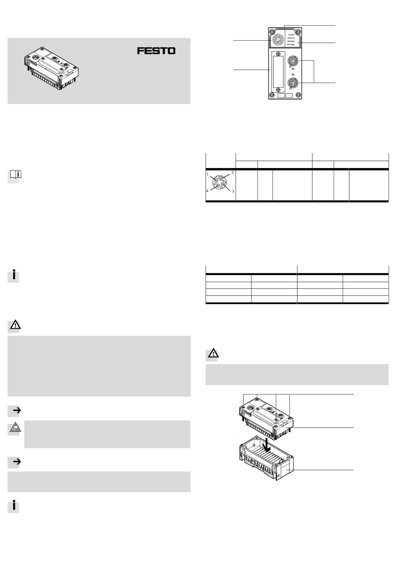
3Connection and display components
1
2
3
4
5
1Rating plate
2Network/CPX-specific LEDs
3Network connections X1 and X2
1)
4Cover for DIL switches
5Service interface CPX-MMI or
CPX-FMT
2)
1)Connection socket: M12, D-coded, 4-pin2)Connection socket: M12, A-coded, 5-pin
Fig. 1
3.1Network connections
Socket
Connection [X1]Connection [X2]
PinSignal/explanationPinSignal/explanation
M12, 4-pin
1
2
3
4
Housing
TX+
RX+
TX–
RX–
FE
Transmitted data +
Received data +
Transmitted data –
Received data –
Screening/FE
1)
1
2
3
4
Housing
RX+
TX+
RX–
TX–
FE
Received data +
Transmitted data +
Received data –
Transmitted data –
Screening/FE
1)
1)The screened connection is connected to the earth potential of the CPX terminal through an RC element.
Fig. 2
3.2LED indicators - normal operating status
Behaviour of the LED indicators in normal operating status:
–The LEDs S, SD, PS and PL illuminate green.
–The LEDs TP1 and TP2 illuminate or flash green.
–The yellow LED (M) illuminates, flashes or is dark.
–The red LED (SF) is dark.
Network-specific LED indicatorsCPX-specific LED indicators
2)
S (green, orange, red)Sercos III
1)
PS (green)Power System
SD (green, orange, red)Sub Device
1)
PL (green)Power Load
TP1 (green)Traffic Port 1SF (red)System Failure
3)
TP2 (green)Traffic Port 2M (yellow)Modify
4)
1)Detailed information (è Description for the module P.BE-CPX-FB39-…)
2)Detailed information (è CPX system description P.BE-CPX-SYS-…)
3)Flashes in case of error, error diagnostics (è CPX system description P.BE-CPX-SYS-…)
4)Parameterisation revised or “Force” active.
Fig. 3
4Mounting and dismantling
Warning
Electrical voltage
Injury caused by electric shock, damage to machine and to system
Switch supply power off before assembly work.
2
3
1
1Screws
2Module
3Interlinking block
Fig. 4
Product specificaties
| Merk: | Festo |
| Categorie: | Niet gecategoriseerd |
| Model: | CPX-FB39 |
Heb je hulp nodig?
Als je hulp nodig hebt met Festo CPX-FB39 stel dan hieronder een vraag en andere gebruikers zullen je antwoorden
Handleiding Niet gecategoriseerd Festo

3 Mei 2026
30 April 2026
29 April 2026
29 April 2026
29 April 2026
29 April 2026
28 April 2026
28 April 2026
28 April 2026
28 April 2026
Handleiding Niet gecategoriseerd
Nieuwste handleidingen voor Niet gecategoriseerd
24 Juli 2026
24 Juli 2026
23 Juli 2026
23 Juli 2026
23 Juli 2026
23 Juli 2026
23 Juli 2026
23 Juli 2026
23 Juli 2026
23 Juli 2026