Elica Fusaro EFS130BL Handleiding
Bekijk gratis de handleiding van Elica Fusaro EFS130BL (20 pagina’s), behorend tot de categorie Afzuigkap. Deze gids werd als nuttig beoordeeld door 86 mensen en kreeg gemiddeld 4.9 sterren uit 2 reviews. Heb je een vraag over Elica Fusaro EFS130BL of wil je andere gebruikers van dit product iets vragen? Stel een vraag
Pagina 1/20
1
LIB0102436
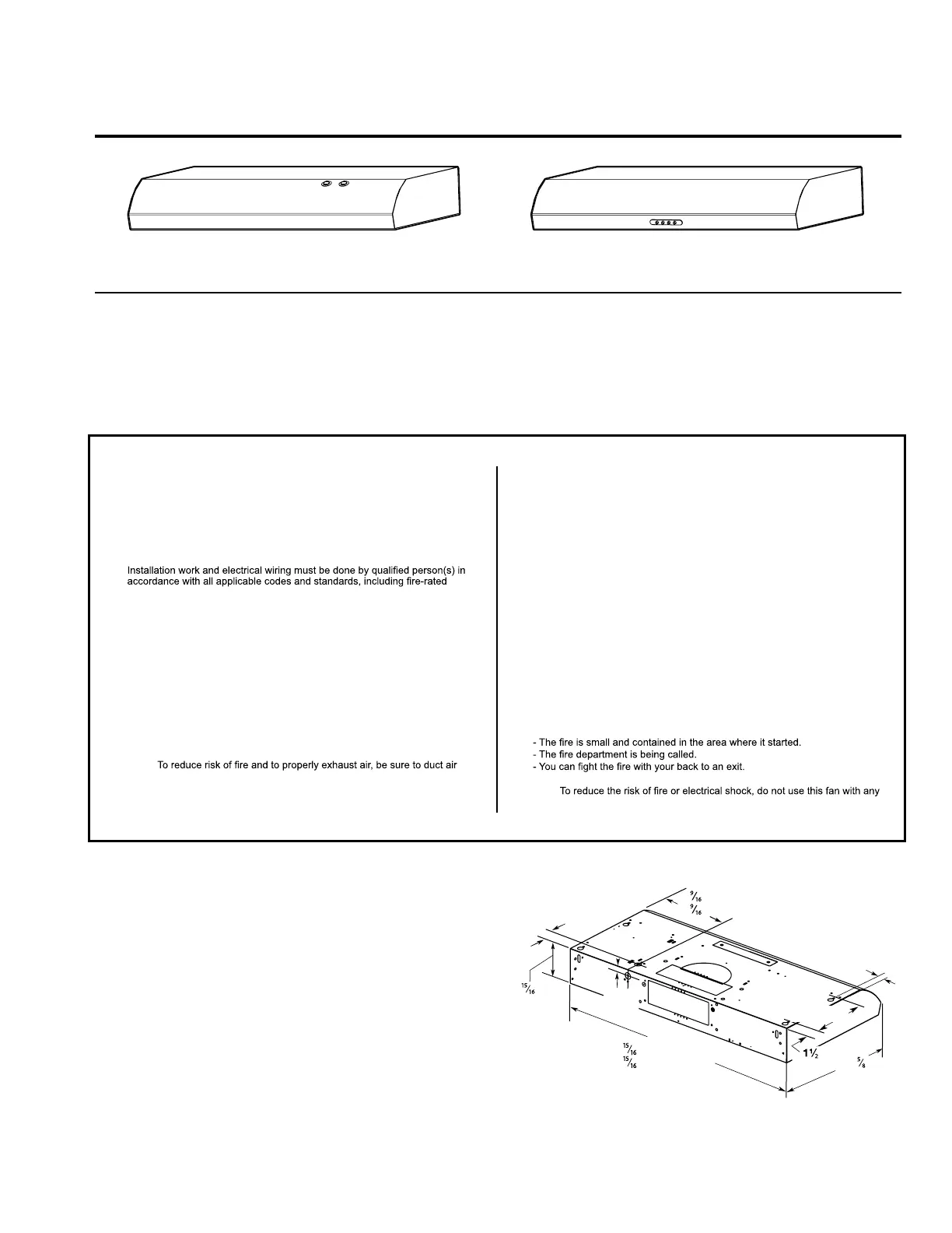
Installation
Instructions Guide
MODELEFS130 MODELSENM230
ENM236
APPROVED FOR RESIDENTIAL APPLIANCES
FOR RESIDENTIAL USE ONLY
READ AND SAVE THESE INSTRUCTIONS
PLEASE READ ENTIRE INSTRUCTIONS BEFORE PROCEEDING.
INSTALLATION MUST COMPLY WITH ALL LOCAL CODES.
IMPORTANT:Save these Instructions for the Local Electrical Inspector’s use.
INSTALLER:Please leave these Instructions with this unit for the owner.
OWNER: Please retain these instructions for future reference.
Safety Warning:Turn off power circuit at service panel and lock out panel before wiring
this appliance.
Requirement 120 VAC, 60 Hz. 15 or 20 A Branch Circuit
IMPORTANT SAFETY INSTRUCTIONS
WARNING: TO REDUCE THE RISK OF FIRE, ELECTRIC SHOCK, OR INJURY TO
PERSONS, OBSERVE THE FOLLOWING:
■Use this unit only in the manner intended by the manufacturer. If you have
questions, contact the manufacturer.
■Before servicing or cleaning the unit, switch power off at service panel and lock
the service disconnecting means to prevent power from being switched on
accidentally. When the service disconnecting means cannot be locked, securely
fasten a prominent warning device, such as a tag, to the service panel.
■
construction.
■Do not operate any fan with a damaged cord or plug. Discard fan or return to an
authorized service facility for examination and/or repair.
■Sufficient air is needed for proper combustion and exhausting of gases through
the flue (chimney) of fuel burning equipment to prevent backdrafting. Follow the
heating equipment manufacturer’s guideline and safety standards such as
those published by the National Fire Protection Association (NFPA), the
American Society for Heating, Refrigeration and Air Conditioning Engineers
(ASHRAE), and the local code authorities.
■When cutting or drilling into wall or ceiling; do not damage electrical wiring and
other utilities.
■Ducted fans must always be vented outdoors.
CAUTION: For general ventilating use only. Do not use to exhaust hazardous or
explosive materials and vapors.
CAUTION:
outside - do not vent exhaust air into spaces within walls or ceilings, attics or into
crawl spaces, or garages.
WARNING: TO REDUCE THE RISK OF FIRE, USE ONLY METAL DUCTWORK
WARNING: TO REDUCE THE RISK OF A RANGE TOP GREASE FIRE:
■Never leave surface units unattended at high settings. Boilovers cause smoking
and greasy spillovers that may ignite. Heat oils slowly on low or medium
settings.
■Always turn hood ON when cooking at high heat or when flambeing food
(i.e. Crepes Suzette, Cherries Jubilee, Peppercorn Beef Flambé).
■Clean ventilating fans frequently. Grease should not be allowed to accumulate
on fan or filter.
■Use proper pan size. Always use cookware appropriate for the size of the
surface element.
WARNING: TO REDUCE THE RISK OF INJURY TO PERSONS IN THE EVENT OF A
RANGE TOP GREASE FIRE, OBSERVE THE FOLLOWING:
a
■SMOTHER FLAMES with a close fitting lid, cookie sheet, or metal tray, then
turn off the burner. BE CAREFUL TO PREVENT BURNS. If the flames do not
go out immediately, EVACUATE AND CALL THE FIRE DEPARTMENT.
■NEVER PICK UP A FLAMING PAN - you may be burned.
■DO NOT USE WATER, including wet dishcloths or towels - a violent steam
explosion will result.
■Use an extinguisher ONLY if:
- You know you have a class ABC extinguisher, and you already know how to
operate it.
a
Based on “Kitchen Fire Safety Tips” published by NFPA.
WARNING:
solid-state speed control device.
READ AND SAVE THIS INSTRUCTIONS
LOCATION REQUIREMENTS
IMPORTANT:Observe all governing codes and ordinances.
■It is the installer’s responsability to comply with installation clearances specified on
the model/serial rating plate. The model/serial rating plate is located inside the
range hood on the left wall.
■Range hood location should be away from strong draft areas, such as windows,
doors and strong heating vents.
■Cabinet opening dimensions that are shown must be used. Given dimensions
provide minimum clearance. Consult the cooktop/range manufacturer installation
instructions before making any cutouts.
■Grounded electrical outlet is required. See “Electrical Requirements” section.
■All openings in ceiling and wall where range hood will be installed must be sealed.
■These range hoods are factory set for vented installations.
Models that are capable of being installed as non-vented (recirculating) require
charcoal filters. See the “Accessories” section to order recirculation kit.
PRODUCT DIMENSIONS
1"
(2,5 cm)
4"
(12,5 cm)
6" (16,7 cm) or
9
" (24,4 cm)
29" (76,0 cm)
or
35
" (91,0 cm)
18
"
(47,3 cm)
"
(3,8 cm)
9"
(22,9 cm)
2"
(5,1 cm)
1"
(2,5 cm)
Product specificaties
| Merk: | Elica |
| Categorie: | Afzuigkap |
| Model: | Fusaro EFS130BL |
Heb je hulp nodig?
Als je hulp nodig hebt met Elica Fusaro EFS130BL stel dan hieronder een vraag en andere gebruikers zullen je antwoorden
Handleiding Afzuigkap Elica

22 September 2025
7 Augustus 2025
29 Maart 2025
2 December 2024
2 December 2024
2 December 2024
2 December 2024
2 December 2024
2 December 2024
2 December 2024
Handleiding Afzuigkap
Nieuwste handleidingen voor Afzuigkap
4 Juni 2026
4 Juni 2026
3 Juni 2026
3 Juni 2026
3 Juni 2026
3 Juni 2026
3 Juni 2026
2 Juni 2026
1 Juni 2026
1 Juni 2026