Dell PowerConnect J-SRX240 Handleiding
Dell
Niet gecategoriseerd
PowerConnect J-SRX240
Bekijk gratis de handleiding van Dell PowerConnect J-SRX240 (73 pagina’s), behorend tot de categorie Niet gecategoriseerd. Deze gids werd als nuttig beoordeeld door 2 mensen en kreeg gemiddeld 4.7 sterren uit 1.5 reviews. Heb je een vraag over Dell PowerConnect J-SRX240 of wil je andere gebruikers van dit product iets vragen? Stel een vraag
Pagina 1/73

Use the instructions in this quick start to help you connect the Dell PowerConnect
J-Series J-SRX240 Services Gateway to your network. For details, see the J-SRX240
Services Gateway Hardware Guide at http://support.dell.com/manuals. (Regulatory
model number SRX240)
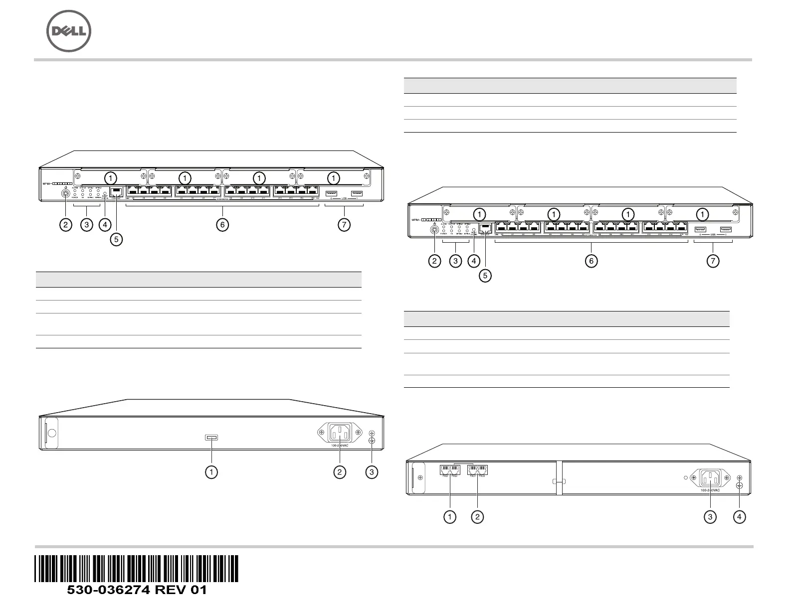
J-SRX240 Services Gateway (J-SRX240B, J-SRX240H) Front Panel
J-SRX240 Services Gateway (J-SRX240B, J-SRX240H, J-SRX240H-POE)
Back Panel
J-SRX240 Services Gateway with Integrated Convergence Services
(J-SRX240H-POE, J-SRX240H-P-MGW) Front Panel
J-SRX240 Services Gateway with Integrated Convergence Services
(J-SRX240H-P-MGW) Back Panel
Callout Description Callout Description
1 Mini-PIM slots 5 Console port
2 Power button 6 Gigabit Ethernet (0/0 to 0/15)
3 LEDs (ALARM, POWER,
STATUS, HA, mPIM)
7 USB ports
4 Reset Config button
Callout Description
1 Cable tie holder
2 Power supply input
3 Grounding point
Callout Description Callout Description
1 Mini-PIM slots 5 Console port
2 Power button 6 Gigabit Ethernet (0/0 to 0/15)
3 LEDs (ALARM, POWER,
STATUS, HA, mPIM)
7 USB ports
4 Reset Config button
037518
Dell PowerConnect J-Series J-SRX240 Services Gateway
Quick Start

Page 2
J-SRX240 Services Gateway Models
The following four models of J-SRX240 Services Gateway are available:
NOTE:
On the J-SRX240H-PoE and J-SRX240H-P-MGW models, Power over Ethernet
(PoE) of 150 watts is supported across all 16 ports (ge-0/0/0 to ge-0/0/15).
Connecting and Configuring the J-SRX240 Services Gateway
Use the instructions below to connect and set up any model of the J-SRX240 Services
Gateway to protect your network. Refer to the LEDs on the front panel of the device to
help you determine the status of the device.
Part 1: Connect the Services Gateway to Earth Ground
1. Obtain a grounding cable—14 AWG single-strand, 4 A—with a ring-type,
vinyl-insulated TV14-6R lug or equivalent attached by a licensed electrician.
2. Connect the grounding cable to a proper earth ground.
3. Place the grounding cable lug over the grounding point on the upper rear of the
chassis, and secure the lug with one 6-32 UNC screw.
Part 2: Connect the Power Cable to the Device
Connect the power cable to the device and a power source. We recommend using a
surge protector. Note the following indications:
POWER LED (green): The device is receiving power.
STATUS LED (green): The device is operating normally.
ALARM LED (amber): The device is operating normally, and may glow amber as a
rescue configuration has not been set. This is not a panic condition.
mPIM LED (off): The Mini-Physical Interface Module (Mini-PIM) is not present or is
not detected by the device. If this LED is green and steadily on, it indicates that the
Mini-PIM is functioning normally.
NOTE:
After a rescue configuration has been set, an amber ALARM LED indicates a
minor alarm, and a solid red ALARM LED indicates that a major problem exists on the
services gateway.
NOTE:
You must allow the device between 5 and 7 minutes to boot up after you have
powered it on. Wait until the STATUS LED is solid green before proceeding to the next
part.
Part 3: Connect the Management Device
Connect the management device to the services gateway using either of the following
methods:
Connect an RJ-45 cable (Ethernet cable) from any one port between ge-0/0/1 and
ge-0/0/15 on the front panel to the Ethernet port on the management device
(workstation or laptop).
We recommend this connection method. If you are using this method to connect,
proceed with Part 4.
Connect an RJ-45 cable (Ethernet cable) from the port labeled CONSOLE to the
supplied DB-9 adapter, which then connects to the serial port on the management
device. (Serial port settings: 9600 8-N-1.)
If you are using this method to connect, proceed with the CLI configuration
instructions available in the Branch SRX Series Services Gateways Golden
Configurations at http://www.juniper.net/us/en/local/pdf/app-notes/3500153-en.pdf.
See the illustration below for details on connecting a management interface:
Callout Description
1 FXS voice port
2 FXO voice port
3 Power supply input
4 Grounding point
Device DDR Memory Power over Ethernet Voice Support
J-SRX240B 512 MB No No
J-SRX240H 1 GB No No
J-SRX240H-POE 1 GB Yes No
J-SRX240H-P-MGW 1 GB Yes Yes
Product specificaties
Merk: | Dell |
Categorie: | Niet gecategoriseerd |
Model: | PowerConnect J-SRX240 |
Heb je hulp nodig?
Als je hulp nodig hebt met Dell PowerConnect J-SRX240 stel dan hieronder een vraag en andere gebruikers zullen je antwoorden
Handleiding Niet gecategoriseerd Dell
29 Juli 2025
14 April 2025
14 April 2025
3 December 2024
3 December 2024
3 December 2024
3 December 2024
3 December 2024
3 December 2024
3 December 2024
Handleiding Niet gecategoriseerd
- Eschenbach
- Luxli
- MJX
- Silver Cross
- Velbus
- Jenn-Air
- Viridian
- Bugaboo
- Midea
- JAYS
- Dualit
- Weil
- The Joy Factory
- Meade
- Ergobaby
Nieuwste handleidingen voor Niet gecategoriseerd
2 Augustus 2025
2 Augustus 2025
2 Augustus 2025
2 Augustus 2025
2 Augustus 2025
2 Augustus 2025
2 Augustus 2025
2 Augustus 2025
2 Augustus 2025
2 Augustus 2025