Crestron HD-MD-400-C-E Handleiding
Crestron Niet gecategoriseerd HD-MD-400-C-E
Bekijk gratis de handleiding van Crestron HD-MD-400-C-E (2 pagina’s), behorend tot de categorie Niet gecategoriseerd. Deze gids werd als nuttig beoordeeld door 19 mensen en kreeg gemiddeld 4.1 sterren uit 3 reviews. Heb je een vraag over Crestron HD-MD-400-C-E of wil je andere gebruikers van dit product iets vragen? Stel een vraag
Pagina 1/2
DOGUIDE
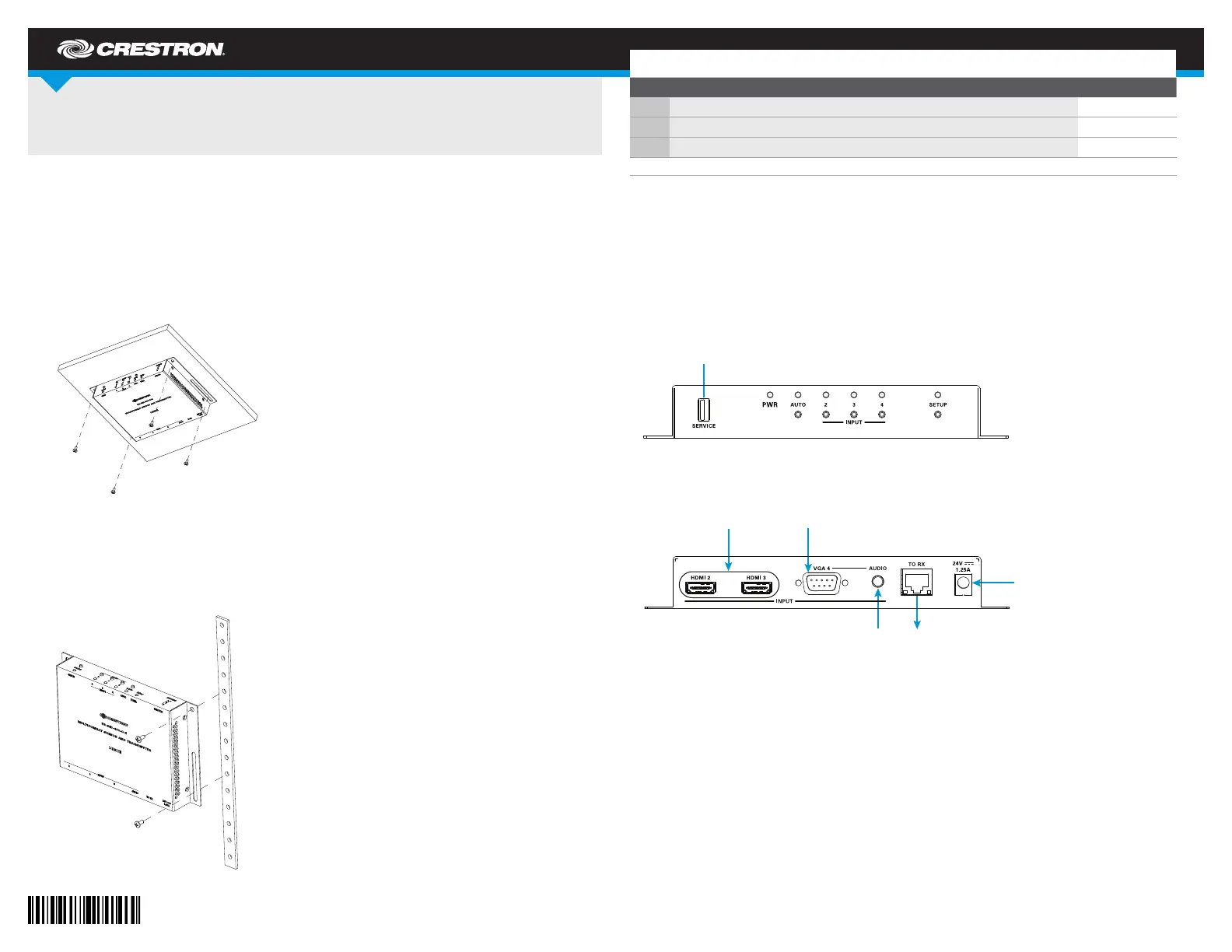
DO Connect the Devices
Make connections to the top and bottom panels of the devices as required for the application.
NOTE: Only one 24 Vdc power pack (included) is required to power both the transmitter and
the receiver; therefore, connect the power pack to the 24 Vdc power connector of either the
transmitter or receiver. Power is transmitted over the cable that connects the TO RX link output
port of the transmitter to the FROM TX link input port of the receiver.
Top and Bottom Panel Connections of the HD-MD-400-C-E Transmitter
HD-MD-400-C-E
HD Scaling Auto-Switcher and Extender 400
DO Install the Devices
The HD-MD-400-C-E is a multiformat switcher that consists of a transmitter and a receiver.
The transmitter and receiver can be mounted onto a at surface or onto a rack rail.
Mounting onto a Flat Surface
Using four mounting screws (not included), mount the transmitter and receiver onto a at
surface such as the underside of a table or onto a wall as appropriate for the installation.
Mounting to the Underside of a Table
Mounting onto a Rack Rail
The transmitter and receiver can be mounted onto the front or rear rail of a rack. Position either
the left or right mounting ange of the device so that the holes align with the holes in the rack.
Then, secure the device to the rack using two mounting screws (not included).
Mounting onto a Rack Rail
DO Check the Box
QTYPRODUCTCOLORPART NUM.
1Connector, 2-Pin2003574
2Connector, 5-Pin2003577
1Power Pack, 24 Vdc 1.25 A, 100-240 Vac2045870
Not included: Cables, Mounting Screws
From HDMI
®
Audio/Video
Sources
From RGB (VGA)
or Component
Video Source
Unbalanced
Stereo Line Level
Audio Input
To FROM TX
Link Input of
HD-MD-400-C-E
Receiver
From 24 VDC
Power Pack
(Included for
Connection to
Transmitter or
Receiver)
Bottom
Panel
For Factory
Use Only
Top
Panel
Product specificaties
| Merk: | Crestron |
| Categorie: | Niet gecategoriseerd |
| Model: | HD-MD-400-C-E |
| Kleur van het product: | Zwart |
| Materiaal behuizing: | Metaal |
| LED-indicatoren: | Ja |
| AC-adapterfrequentie: | 50/60 Hz |
| AC-adapter ingangsspanning: | 100-240 V |
| Ondersteunde video-modi: | 480i, 480p, 576i, 576p, 720p, 1080i, 1080p |
| HDCP: | Ja |
| VGA (D-Sub) invoer ports: | 1 |
| Impedantie: | 200 Ohm |
| RJ-45 ports hoeveelheid: | 3 |
| HDMI in: | 3 |
| Aantal HDMI-uitgangen: | 1 |
| Warmtedissipatie: | 44.3 BTU/h |
| Stroomverbruik (typisch): | 13 W |
| Bedrijfstemperatuur (T-T): | 0 - 40 °C |
| Relatieve vochtigheid in bedrijf (V-V): | 20 - 90 procent |
| Ingangsstroom AC-adapter: | 0.8 A |
| Geschaalde resoluties: | 640 x 480,800 x 600,1024 x 768,1280 x 1024,1280 x 720,1280 x 768,1280 x 800,1360 x 768,1366 x 768,1400 x 1050,1440 x 900,1600 x 1200,1600 x 900,1680 x 1050,1920 x 1200 |
| Kanaal scheiding (1 kHz): | 80 dB |
| Maximale pixelsnelheid: | 165 MHz |
| Baudrate: | 115200 Bd |
Heb je hulp nodig?
Als je hulp nodig hebt met Crestron HD-MD-400-C-E stel dan hieronder een vraag en andere gebruikers zullen je antwoorden
Handleiding Niet gecategoriseerd Crestron

26 Mei 2026
7 Maart 2026
4 Maart 2026
28 Januari 2026
27 Januari 2026
4 December 2025
3 December 2025
2 December 2025
2 December 2025
2 December 2025
Handleiding Niet gecategoriseerd
Nieuwste handleidingen voor Niet gecategoriseerd
23 Juli 2026
23 Juli 2026
23 Juli 2026
23 Juli 2026
23 Juli 2026
23 Juli 2026
23 Juli 2026
23 Juli 2026
23 Juli 2026
22 Juli 2026