Crestron CLXI-4IND Handleiding
Crestron Niet gecategoriseerd CLXI-4IND
Bekijk gratis de handleiding van Crestron CLXI-4IND (4 pagina’s), behorend tot de categorie Niet gecategoriseerd. Deze gids werd als nuttig beoordeeld door 75 mensen en kreeg gemiddeld 4.8 sterren uit 3 reviews. Heb je een vraag over Crestron CLXI-4IND of wil je andere gebruikers van dit product iets vragen? Stel een vraag
Pagina 1/4
CLTI- & CLXI-2IND/4IND
Functional Summary
NOTE: Inductor modules and terminal blocks should be
installed above the dimmer modules, towards the top of
the CAEN or CAENIB enclosure.
The CLTI/CLXI-2IND is a 2-inductor terminal block and
module kit while the CLTI/CLXI-4IND is a 4-inductor
terminal block and module kit. Inductor modules are
typically used to reduce hum from incandescent lamps
that are connected to dimmer modules in a Crestron
lighting system. These kits can be mounted in any
Crestron Automation Enclosure (CAEN or CAENIB-
Series Enclosures). The terminal block is for connecting
wires into and out of the inductor module. The inductor is
wired in series between the output of the dimmer module
and the load. The maximum load for any inductor in the
module is 10 amps.
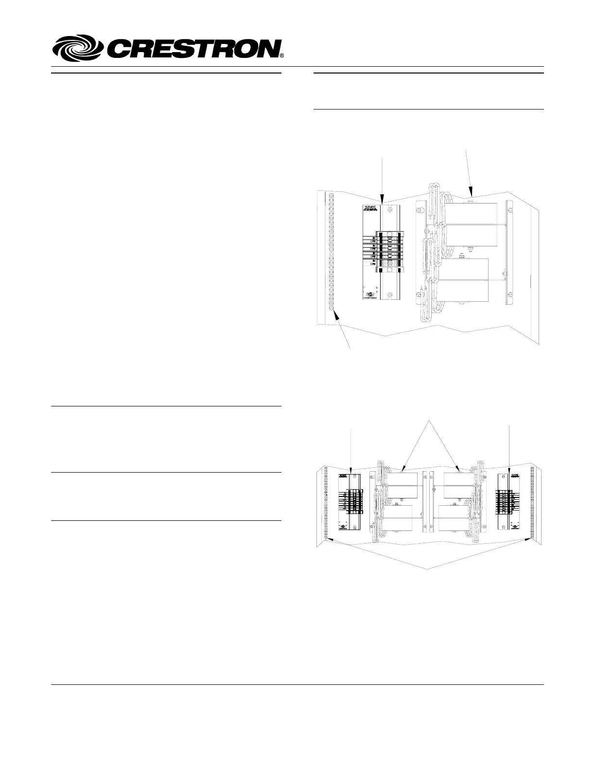
Terminal Block & Module Locations in Single-wide Enclosure
(CLTI/CLXI-4IND shown)
TERMINAL BLOCK
(LEFT)
MODULE
GROUNDING
TERMINAL BLOCK
Each of these Terminal Block and Module kits is
considered single entities and must be used together. The
terminal blocks (CLTI-2IND and/or CLTI-4IND) are
shipped separately from their respective modules
(CLXI-2IND and CLXI-4IND) to permit termination of
the field wiring to the terminal block prior to installation
of the module, as described in this guide.
CLXI-2IND and CLXI-4IND modules can also be
connected to CLTIBN-2IND and CLTIBN-4IND terminal
blocks. For installation information, refer to the latest
version of the CLTIBN Installation Guide (Doc. 6561)
which is available for download from the Crestron
website (www.crestron.com/manuals).
Terminal Block & Module Locations in Double-wide
Enclosure (CLTI/CLXI-4IND shown)
Installation
GROUNDING
TERMINAL
BLOCKS
TERMINAL BLOCK
(LEFT)
MODULES
TERMINAL BLOCK
(RIGHT)
The terminal block and module must be mounted into a
Crestron Automation Enclosure by a licensed electrician,
in accordance with all national and local codes.
CAUTION: This equipment is for indoor use only.
Mount in a well-ventilated area. The ambient temperature
must be 0°C to 40°C (32°F to 104°F). The relative
humidity must be 10% to 90% (non-condensing).
Terminal blocks are installed along the left side of single-
wide enclosures and along the outside edges (left and
right sides) of double-wide enclosures. Modules are
installed along the right side of single-wide enclosures
and side-by-side in the center of double-wide enclosures.
When installing modules and terminal blocks in a double-
wide enclosure, be sure to invert units on the right side so
that they can be properly wired. Refer to the illustrations
shown in the next column when considering the location
of terminal blocks and modules within an enclosure.
Crestron Electronics, Inc.Installation Guide – DOC. 6559A
15 Volvo Drive Rockleigh, NJ 07647(2017224)
Tel: 888.CRESTRON04.07
Fax: 201.767.7576Specifications subject to
www.crestron.comchange without notice.
Product specificaties
| Merk: | Crestron |
| Categorie: | Niet gecategoriseerd |
| Model: | CLXI-4IND |
Heb je hulp nodig?
Als je hulp nodig hebt met Crestron CLXI-4IND stel dan hieronder een vraag en andere gebruikers zullen je antwoorden
Handleiding Niet gecategoriseerd Crestron

26 Mei 2026
7 Maart 2026
4 Maart 2026
28 Januari 2026
27 Januari 2026
4 December 2025
3 December 2025
2 December 2025
2 December 2025
2 December 2025
Handleiding Niet gecategoriseerd
Nieuwste handleidingen voor Niet gecategoriseerd
23 Juli 2026
23 Juli 2026
23 Juli 2026
23 Juli 2026
23 Juli 2026
23 Juli 2026
23 Juli 2026
23 Juli 2026
23 Juli 2026
22 Juli 2026