Crestron CLXI-1DIM4 Handleiding


Lees hieronder de đź“– handleiding in het Nederlandse voor Crestron CLXI-1DIM4 (6 pagina's) in de categorie Niet gecategoriseerd. Deze handleiding was nuttig voor 21 personen en werd door 2 gebruikers gemiddeld met 4.5 sterren beoordeeld

Pagina 1/6
CLTI- & CLXI-1DIM4
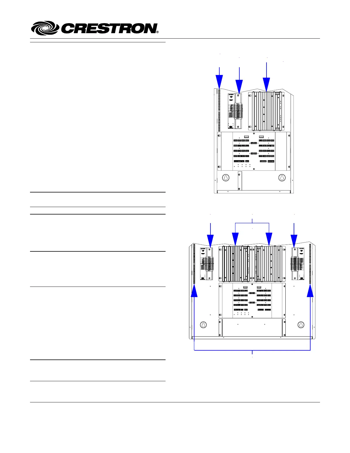
Terminal Block & Module Locations (Single-wide Enclosure)
Functional Summary
GROUNDING
TERMINAL
BLOCK
TERMINAL
BLOCK
MODULE
(INSTALL INTO
LOWEST
AVAILABLE
SPACES)
The Crestron 1-Feed, 4-Dimmer Terminal Block and
Module (CLTI-1DIM4 and CLXI-1DIM4, respectively),
are considered a single entity and must be used together.
They ship separately to permit termination of the field
wiring to the CLTI-1DIM4 prior to installation of the
CLXI-1DIM4, as described in this guide. They can be
mounted in any Crestron Automation Enclosure (CAEN
or CAENIB-Series Enclosures). The terminal block is
designed to terminate the circuit feed (LINE and
NEUTRAL) and distribute the controlled circuit (LOAD)
to the fixtures. The module connects to the terminal block
and performs dimming control of four incandescent,
magnetic low voltage, neon, cold cathode, or dimmable
2-wire fluorescent lighting loads. The maximum load is
10 amps for any controlled circuit, limited to 13 amps
total per module. The unit requires 230VAC 50 Hz,
1 phase input voltage. An oversize heat sink dissipates
heat efficiently. There are LEDs on the module to indicate
communication to a Cresnet network, input power to the
module, and output power to the load.
NOTE: When connecting to an Arc Fault Breaker, the
load should not exceed 1000 watts. Terminal Block & Module Locations (Double-wide Enclosure)
TERMINAL BLOCK
(RIGHT)
GROUNDING TERMINAL BLOCKS
TERMINAL BLOCK
(LEFT)
MODULE
(INSTALL INTO
LOWEST
AVAILABLE
SPACES)
Installation
Terminal block and module must be mounted into a
Crestron Automation Enclosure by a licensed electrician,
in accordance with all national and local codes.
CAUTION: This equipment is for indoor use only and
needs to be air-cooled. Mount in a well-ventilated area.
The ambient temperature must be 0°C to 40°C (32°F to
104°F). The relative humidity must be 0% to 90% (non-
condensing).
Terminal blocks are installed along the left side of single-
wide enclosures and along the outside edges (left and
right sides) of double-wide enclosures. Modules are
installed along the right side of single-wide enclosures
and side-by-side in the center of double-wide enclosures.
When installing modules and terminal blocks in a double-
wide enclosure, be sure to invert units on the right side so
that they can be properly wired. Refer to the illustrations
shown below when considering the location of terminal
blocks and modules within an enclosure.
NOTE: Modules and terminal blocks must be installed
into the lowest available spaces and continue toward the
top of the enclosure.
Crestron Electronics, Inc. Installation Guide – DOC. 6406A
15 Volvo Drive Rockleigh, NJ 07647 (2013814)
Tel: 888.CRESTRON 11.07
Fax: 201.767.7576 Specifications subject to
www.crestron.com change without notice.
Terminal Block & Module Crestron CLTI- & CLXI-1DIM4
2 – • Terminal Block & Module: CLTI- - & CLXI 1DIM4 Installation Guide DOC. 6406A
Terminal Block Installation and Field
Wiring
NOTE: To install a CLTIBN Circuit Breaker Terminal
Block, refer to the latest version of the CLTIBN
Installation Guide (Doc. 6561) which can be downloaded
from the Crestron website (www.crestron.com/manuals).
NOTE: Both left- -side and right side adhesive wiring
labels are provided. The left-side labels are used in both
single and double- -wide enclosures. The right side labels
are only used in double-wide enclosures.
1. Remove the backing from the left or right
adhesive wiring label.
2. Apply the adhesive label by aligning the holes in
the label with the appropriate holes on the
Crestron Automation Enclosure where the
terminal block is to be mounted. For information
on mounting locations, refer to the latest version
of the CAEN Installation Guide (Doc. 5940) or
the CAENIB Installation Guide (Doc. 6562). The
wiring label lies beneath the terminal block as
shown in the two wiring diagrams on this page.
3. Use the two supplied self-tapping pan Phillips
screws (8B x ÂĽ (6 mm) length) to secure the
terminal block to the Crestron Automation
Enclosure.
CAUTION: A bypass jumper is provided to allow
testing and to protect the module during installation.
When properly secured by five screws, the bypass
jumper on the brown and red section of the terminal
block shorts the LINE in to DIM out so that the
circuit is energized. Do not remove the bypass
jumper until all feed and load wiring has been
completed, the circuit has been tested for electrical
faults, and the module has been installed. Refer to
“Module Installation” on next page.
Furthermore, the jumper on the blue section of the
terminal block ties the neutral in to the neutral outs.
This jumper should never be removed.
NOTE: Use copper conductors only – rated 75°C
4. With the circuit breakers turned off, connect the
circuit feed (LINE and NEUTRAL) and
controlled circuit (LOAD) wires to the terminal
block per the markings provided on the wiring
label (as shown in the diagrams on this page).
Terminal blocks accept one 2.5 - 6.0 mm
2 wire.
Wires should be stripped to 12 mm. Tighten
terminal blocks to 1 Nm.
5. Grounding terminal blocks are available in the
cabinet for termination of ground wires. Tighten
to 4 Nm (2.5 - 6.0 mm2), 4.5 Nm (10.0 mm2), or
5.1 Nm (16 - 25 mm2).
6. Test the circuit for electrical faults by turning on
the circuit breaker, checking that the breaker
does not trip, and that power is delivered to the
proper loads.
NOTE: If installing in a CAENIB, complete the
installation with a CAENIB-BP Blank Plate. Refer to the
latest version of the CAENIB-BP Installation Guide (Doc.
6563) for details.
Wiring Diagram of the Terminal Block to the Feed and
Load(s)(Single- -wide and Left Side Double wide Enclosures)
TERMINAL
BLOCK
GROUNDING
TERMINAL
BLOCK
GND
LEFT SIDE
WIRING LABEL
TO
LOAD(S)
AREA FOR
MODULE
LOCATION
LABEL
(FROM 16 AMP
CIRCUIT BREAKER)
NEUTRAL
LINE
BYPASS
JUMPER
Wiring Diagram of the Terminal Block to the Feed and
Load(s) (Right Side Double-wide Enclosures)
TERMINAL
BLOCK
RIGHT SIDE
WIRING LABEL
BYPASS
JUMPER
NEUTRAL
(FROM 16 AMP
CIRCUIT
BREAKER)
AREA FOR
MODULE
LOCATION
LABEL
TO
LOAD(S)
GROUNDING
TERMINAL
BLOCK
LINE
GND
Crestron CLTI- - & CLXI 1DIM4 Terminal Block & Module
Installation Guide – 3 DOC. 6406A Terminal Block & Module: CLTI- - & CLXI 1DIM4 •
Module Installation
CAUTION: Module contains electrostatic sensitive
devices (ESDs); unit must be handled from metal chassis
– do not touch PC board or components.
NOTE: Modules are to be installed after enclosure has
been completely wired. Refer to the terminal block
installation procedure on page 2 for details.
1. Use the four supplied self-tapping pan Phillips
screws (8B x ÂĽ-inch (6 mm) length) to secure
the module to the enclosure.
2. As shown in the wiring diagrams (next column),
connect the wires from the module to the
terminal block. Each wire exits the module
directly in line with, and is the same color as, the
terminal to which it should be connected. Wires
are pre-stripped to 12 mm. Tighten to 1 Nm.
3. If the module is being installed above another
module within the enclosure, attach the supplied
module interconnect cable between the two
modules. The illustration below depicts the area
within a double-wide enclosure where the
corners of four modules meet.
NOTE: One wire on the module interconnect cable
may be a different color from the rest. The color has
no bearing on its orientation during installation.
Use Module Interconnect Cable to Wire Module to Module
MODULE
INTERCONNECT
CABLE ATTACHED
CONNECTION
NOT
MADE
4. Turn on the circuit breaker and verify that the
green PWR LED on the module lights, the
breaker does not trip, and power is delivered to
the loads.
5. Turn off the circuit breaker and remove the five-
position bypass jumper on the brown and red
section of the terminal block. The bypass jumper
on the blue section of the terminal block remains
installed. Refer to the figures in the next column
for a close-up of the jumpers.
NOTE: Before the five-position bypass jumper,
shown in the illustration, is removed, the Crestron
Professional Automation Computer (PAC2), which
provides control to the system, should be properly
connected and contain a valid program to provide
control of the module.
Wiring Diagram of the Terminal Block to the Module
(Single- -wide and Left Side Double wide Enclosures)
BYPASS JUMPER ON BROWN AND
RED SECTION OF TERMINAL
BLOCK HAS BEEN REMOVED
AFTER LOOSENING ALL SCREWS.
JUMPER ON BLUE SECTION
IS NOT REMOVED.
BLUE
BROWN
RED
ENLARGEMENT DETAIL:
JUMPER INSTALLED
BYPASS JUMPER
REMOVED
Wiring Diagram of the Terminal Block to the Module
(Right Side Double-wide Enclosures)
BLUE
BROWN
RED
BYPASS JUMPER ON BROWN AND
RED SECTION OF TERMINAL
BLOCK HAS BEEN REMOVED
AFTER LOOSENING ALL SCREWS.
JUMPER ON BLUE SECTION
IS NOT REMOVED.
ENLARGEMENT DETAIL:
BYPASS JUMPER
REMOVED
JUMPER INSTALLED
6. Turn on the circuit breaker.
NOTE: Power must be supplied to LINE for the
module to communicate with the control system or
for any of the circuits to operate.


Product specificaties

Merk: Crestron
Categorie: Niet gecategoriseerd
Model: CLXI-1DIM4

Heb je hulp nodig?

Als je hulp nodig hebt met Crestron CLXI-1DIM4 stel dan hieronder een vraag en andere gebruikers zullen je antwoorden


Handleiding Niet gecategoriseerd Crestron

Handleiding Niet gecategoriseerd

Nieuwste handleidingen voor Niet gecategoriseerd