Citronic D1000 Handleiding
Bekijk gratis de handleiding van Citronic D1000 (84 pagina’s), behorend tot de categorie Receiver. Deze gids werd als nuttig beoordeeld door 59 mensen en kreeg gemiddeld 4.1 sterren uit 5 reviews. Heb je een vraag over Citronic D1000 of wil je andere gebruikers van dit product iets vragen? Stel een vraag
Pagina 1/84
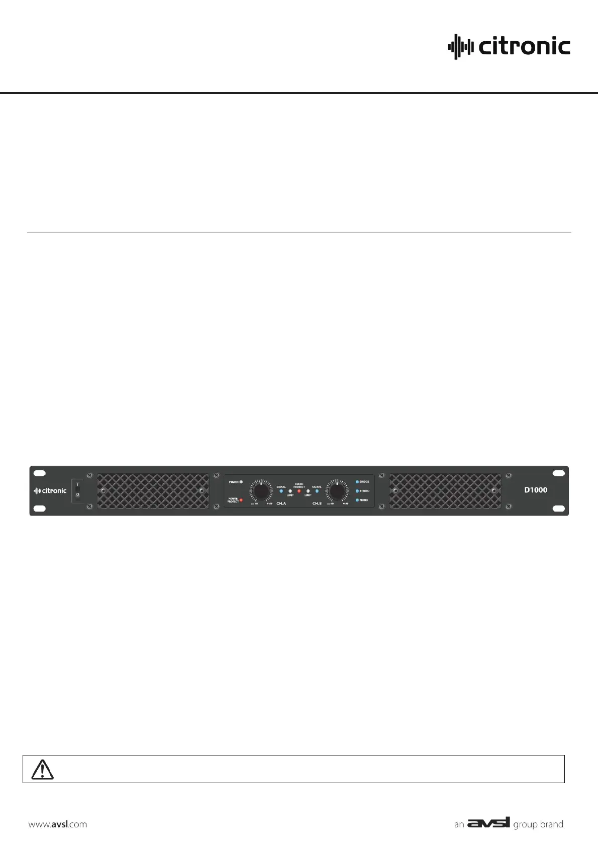
D1000
CLASS-D POWER AMPLIFIER
Order ref: 172.110UK
User Manual
Version 1.0
Caution: Please read this manual carefully before operating
Damage caused by misuse is not covered by the warranty
Product specificaties
| Merk: | Citronic |
| Categorie: | Receiver |
| Model: | D1000 |
| Kleur van het product: | Zwart |
| Gewicht: | 3930 g |
| Breedte: | 482 mm |
| Diepte: | 245 mm |
| Hoogte: | 44 mm |
| Aan/uitschakelaar: | Ja |
| Connectiviteitstechnologie: | Bedraad |
| Bedoeld voor: | Optreden/podium |
| Audio-uitgangskanalen: | - kanalen |
| Signaal/ruis-verhouding: | - dB |
| Totale harmonische vervorming (THD): | - procent |
| XLR in: | Ja |
| XLR out: | 1 |
| Rackcapaciteit: | 1U |
| AC-ingangsspanning: | 220 - 240 V |
| AC-ingangsfrequentie: | 50 - 60 Hz |
| Input sensitiviteit: | 1.44 mV |
| Piekvermogen per kanaal: | - W |
| Versterker klasse: | D |
| Speakers connectiviteit type: | XLR |
| RMS vermogen uitvoer per kanaal (4 Ohm): | 500 W |
| RMS vermogen uitvoer per kanaal (8 Ohm): | 300 W |
| Bridge-mode vermogen uitvoer per kanaal (8 Ohm): | 1000 W |
| Waarde zekering: | T10A |
Heb je hulp nodig?
Als je hulp nodig hebt met Citronic D1000 stel dan hieronder een vraag en andere gebruikers zullen je antwoorden
Handleiding Receiver Citronic

6 Februari 2024
6 Februari 2024
6 Februari 2024
7 Juli 2023
3 Juli 2023
1 Juli 2023
29 Juni 2023
29 Juni 2023
29 Juni 2023
28 Juni 2023
Handleiding Receiver
Nieuwste handleidingen voor Receiver
20 Juli 2026
15 Juli 2026
15 Juli 2026
15 Juli 2026
15 Juli 2026
14 Juli 2026
14 Juli 2026
13 Juli 2026
13 Juli 2026
13 Juli 2026