Best D49M30SB Handleiding
Bekijk gratis de handleiding van Best D49M30SB (44 pagina’s), behorend tot de categorie Afzuigkap. Deze gids werd als nuttig beoordeeld door 10 mensen en kreeg gemiddeld 4.6 sterren uit 8 reviews. Heb je een vraag over Best D49M30SB of wil je andere gebruikers van dit product iets vragen? Stel een vraag
Pagina 1/44
Page 1
SPECIFICATIONS
REFERENCE QTY. REMARKS Project
Location
Architect
Engineer
Contractor
Submitted byDate
Powerful VERTEX
TM
Complete Capture Design rivals the
finest island hoods. Compact design allows the choice of
many cooktop styles, free-standing and built-in ranges for
island or wall applications.
FEATURES
HOUSING:
• Galvanized steel construction
• Left, right, front, or rear discharge
• Flexible installation - can be used with cooktops, rangetops,
slide-in, and free-standing ranges
• 30", 36", or 48" widths - Fits standard-size cabinets (Some
blower configurations may require deeper cabinets.)
•
For indoor domestic use only
CHIMNEY ASSEMBLY:
•Quiet actuation linear drive system
• Chimney rises 18" when activated - ideal for tall pots
•Aluminum mesh filters - easy to remove, dishwasher-safe
• 304 stainless steel chimney - makes cleanup quick and
easy
•4-speed capacitive-touch control, with delay off and filter
clean reminder
• Heat Sentry
TM
adjusts speed of blower in case of excess
heat
• 2-level LED task light. 7W (30"), 14W (36"), 18W (48")
• Up to 100% capture - equal to comparable island hoods
TRIM / DOOR:
• Low profile
• 304 stainless steel construction
• Articulating door to hide chimney when retracted
• Integrated, capacitive-touch UP button
BLOWER (sold separately):
• Compatible with quiet and efficient 600 cfm Flex Blower -
Model PF6
•
Permanently lubricated, thermally-protected motor
•
Neoprene, resilient anti-vibration mounts
• Can be mounted directly to downdraft or mounted remotely
• Uses standard 8" round duct
•Can be rotated on housing to exhaust left, right or down
•Compatible with in-line/exterior blower models:
EB6, EB9*, EB12*, EB15*, ILB3, ILB6, ILB9, ILB11*
*
Recommended models
TYPICAL SPECIFICATION
Downdraft blower system shall be Best
®
Model D49M30SB,
(D49M36SB), (D49M48SB).
Unit to have stainless steel housing. Chimney to rise 18" and have
304 stainless steel contruction for ease of cleaning.
Filters to be aluminum mesh, easy to remove and dishwasher-
safe.
Blower will connect directly to 8" round duct. Remote application
uses 1-7/8" x 19" to 8" round transition (1-7/8" x 19" to 10" round
transition), (8"/10" round plate). Blower to discharge left, (right),
(front), (rear).
Motor shall be mounted to blower assembly with grease resistant
anti-vibration mounts, be removable, and lifetime lubricated.
Unit to include Heat Sentry
TM
, to adjust blower speed in case of
excess heat.
Unit to include trim / door to hide chimney when retracted.
Downdraft system shall operate on 120 VAC and be able to be
plugged into a standard grounded outlet. It will have a 4-speed
blower control, with delay off, and filter clean reminder.
Downdraft shall include 2-level LED task lighting.
Downdraft blower system to be cULus listed.
SPECIFICATIONS
Volts: 120
Hz: 60
Amps: 3.2
Duct: 8" Round
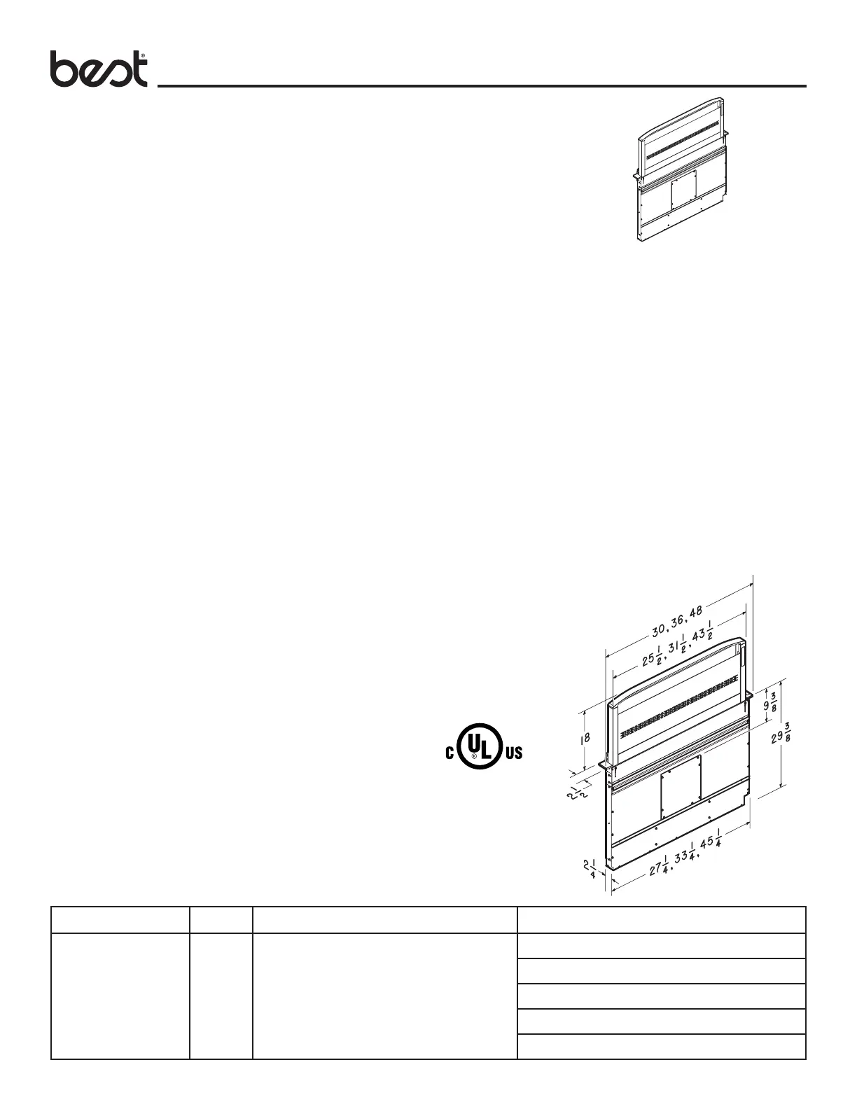
CATTURA
TM
DOWNDRAFT
MODELS D49M30SB,
D49M36SB, D49M48SB
61D 99045243D
BEST Hartford, Wisconsin www.BestRangeHoods.com 800-558-1711
NOTE: Dimensions
shown are for reference
only. Before cutting out
countertop, refer to
instructions packed with
downdraft and cooktop.
Product specificaties
| Merk: | Best |
| Categorie: | Afzuigkap |
| Model: | D49M30SB |
Heb je hulp nodig?
Als je hulp nodig hebt met Best D49M30SB stel dan hieronder een vraag en andere gebruikers zullen je antwoorden
Handleiding Afzuigkap Best

27 Mei 2026
26 Mei 2026
1 September 2025
4 April 2025
26 September 2024
25 Januari 2024
25 Januari 2024
24 Januari 2024
24 Januari 2024
24 Januari 2024
Handleiding Afzuigkap
Nieuwste handleidingen voor Afzuigkap
15 Juni 2026
15 Juni 2026
15 Juni 2026
15 Juni 2026
11 Juni 2026
4 Juni 2026
4 Juni 2026
3 Juni 2026
3 Juni 2026
3 Juni 2026