Berner Pass-Thru Unit 6 Handleiding
Bekijk gratis de handleiding van Berner Pass-Thru Unit 6 (8 pagina’s), behorend tot de categorie Airco. Deze gids werd als nuttig beoordeeld door 3 mensen en kreeg gemiddeld 4.9 sterren uit 2 reviews. Heb je een vraag over Berner Pass-Thru Unit 6 of wil je andere gebruikers van dit product iets vragen? Stel een vraag
Pagina 1/8

-1-
Thank you for choosing Berner.
Berner International has been saving energy and creating healthy, comfortable environments for our customers for over 60 years.
Berner oers unmatched quality, performance, and dependability—not to mention our service. At Berner, we stand behind our products.
TABLE OF CONTENTS
I. UNCRATING............................................................................................................................................................ 2 ........................................................
II. GENERAL MOUNTING INSTRUCTIONS ................................................................................................................................. 3 ...................................
III. WALL MOUNTING ...................................................................................................................................................................................................... 3
IV. SUSPENDED MOUNTING ....................................................................................................................................... 4 ...................................................
V. ELECTRICAL CONNECTIONS 4 .....................................................................................................................................................................................
VI. OPERATING INSTRUCTIONS 5 ....................................................................................................................................................................................
VII. MAINTENANCE AND CLEANING 5 .............................................................................................................................................................................
VIII. SERVICE ............................................................................................................................................................... 6 .....................................................
IX. TROUBLESHOOTING .................................................................................................................................................................................................. 7
X.WARRANTY ................................................................................................................................................ 8 ...................................................................
Installation & Maintenance Instructions
II-400
December, 2022
©Copyright, 2022 Berner International
READ ALL INSTRUCTIONS BEFORE INSTALLING OR USING AIR CURTAIN
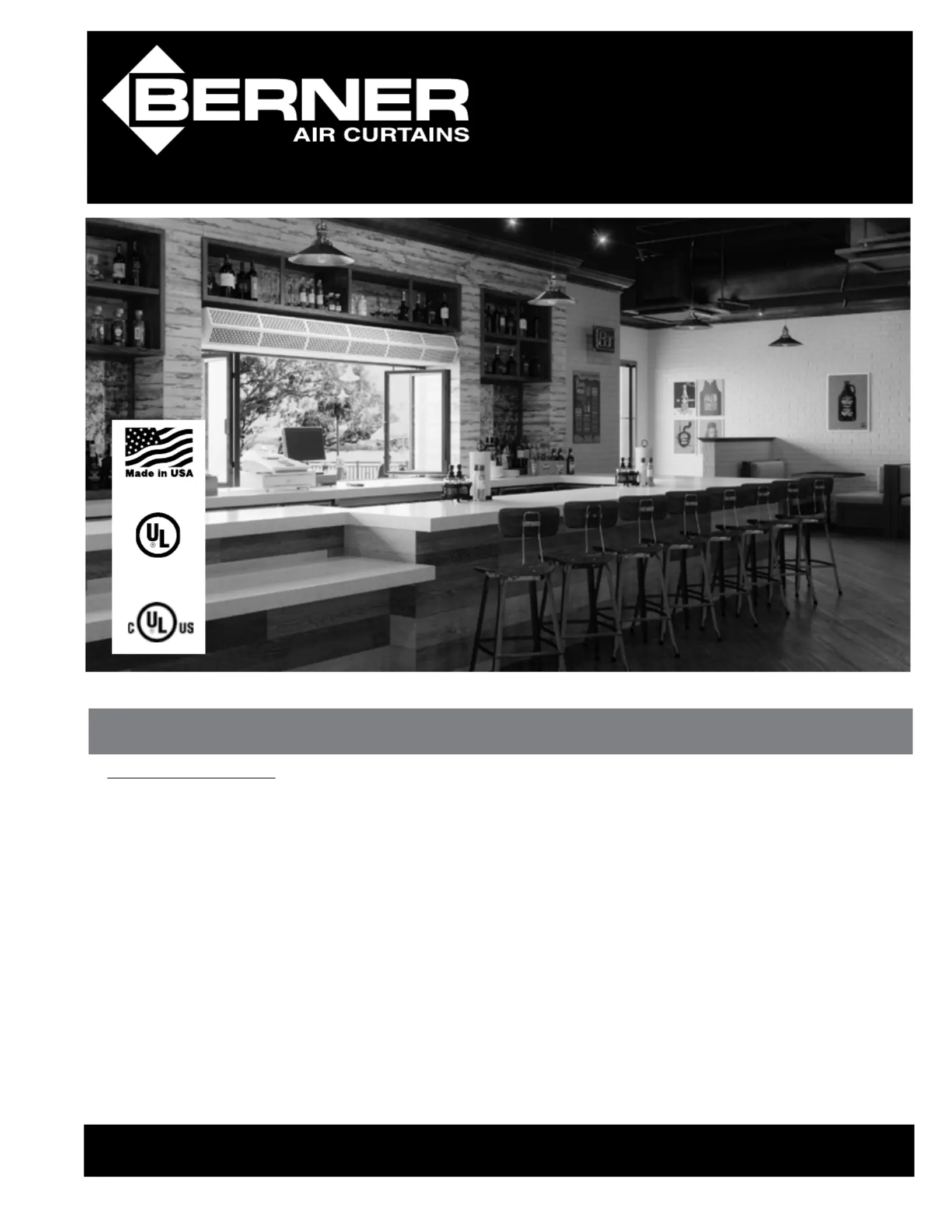
Pass-Thru 6
Air Curtain Series
#PE06 & PT06
www.Berner.com
®
WHEN THE DOORS ARE OPEN
™
save energy & create healthy, comfortable environments
Model #PE06
Model #PT06
for outdoor use

-2-
I. UNCRATING
Carefully examine the carton(s) for damage. If the carton is damaged,
immediately notify the shipping company. Do not delay in ling a
claim. If the air curtain(s) were shipped on wooden skids, remove protec-
tive wood and banding straps securing the carton(s) to the skid. Open
the carton(s) and remove all protective packaging. If the unit will be wall
mounted, remove and save the locking screws from the wall plate and
detach and set aside the wall mounting plate.
Immediately verify that the electrical rating nameplate located on the
cover matches the electrical power supply available. Retain the shipping
carton(s) until the air curtain(s) are installed and properly operating.
ACCESSORIES: If the air curtain(s) were ordered with optional
electrical accessories, the accessories will be found in the carton contain-
ing the air curtain packed in a red bag (marked “additional parts inside”)
or in a separate carton(s) accompanying the air curtain(s).
Check all of the cartons/skids for accessories before discarding.
NOTE: Unheated models come with a remote mounted switch.
A. Read all instructions before installing or using this air curtain.
B. Use this unit only in the manner intended by the manufacturer and described in this manual. Any other use not recommended by the
manufacturer may cause re, electric shock, or injury to persons. If you have any questions, contact the manufacturer.
C. Before servicing or cleaning unit, switch power o at service panel and lock the service disconnecting means to prevent power from
being switched on accidentally. When the service disconnecting means cannot be locked, securely fasten a prominent warning device,
such as a tag, to the service panel.
D. Installation work and electrical wiring must be done by qualied person(s) in accordance with all applicable national and local codes
having jurisdiction, including re-rated construction. See page 4, ELECTRICAL CONNECTIONS (NEC Code ANSI/NFPA No. 70).
E. When cutting or drilling into wall or ceiling, do not damage electrical wiring and other hidden utilities.
F. To reduce the risk of re, do not store or use gasoline or other ammable vapors and liquids in the vicinity of the air curtain.
G. This air curtain is hot when in use. To avoid burns, do not let bare skin touch hot surfaces. Keep combustible materials, such as furniture,
pillows, bedding, papers, clothes, etc. and curtains at least 1 inch from the top, back, front, sides and at least 6 feet from the discharge
of the air curtain.
H. Extreme caution is necessary when any air curtain is used by or near children or invalids, and whenever the heater is left operating
unattended.
I. Do not operate any air curtain after it malfunctions. Disconnect power at the service panel and have the air curtain inspected by a
reputable electrician before reusing.
J. To disconnect the air curtain, turn controls to "o", and turn o power to the air curtain circuit at main disconnect panel.
K. Do not insert or allow foreign objects to enter any ventilation or discharge opening as this may cause an electric shock or re, or
damage the air curtain.
L. To prevent a possible re, do not block the air intake or discharge of the air curtain in any manner.
M. The air curtain has hot and arcing or sparking parts inside. Do not use it in areas where gasoline, paint, or ammable vapors or liquids
are used or stored.
N. This heater may include an audible or visual alarm to warn that parts of the heater are getting excessively hot. If the alarm sounds
(or illuminates), immediately turn the heater o and inspect for any objects on or adjacent to the heater that may have blocked the airow
or otherwise caused high temperatures to have occurred. DO NOT OPERATE THE HEATER WITH THE ALARM SOUNDING (OR ILLUMINATING).
WARNING: TO REDUCE THE RISK OF FIRE, ELECTRIC SHOCK OR INJURY TO PERSONS, OBSERVE THE FOLLOWING:
Model #PE06
Model #PT06
for outdoor use

-3-
TABLE 1 - Weight Charts
FIGURE 2 - Positioning of Air Curtain
II. MOUNTING INSTRUCTIONS (General)
The Pass-Thru 6 air curtain is designed to be an eective barrier
against cold drafts in the winter and hot air in the summer,
ying insects and airborne contaminants. Series# PE06 is UL
certied for Outdoor Mounting and may be mounted inside or
outside, whereas Series# PT06 is UL certied for Indoor Mounting
only. To achieve optimum protection, the unit should be
mounted ush to the wall and as close to the top of the opening
as possible. To ensure peak performance, keep air stream free of
obstructions.
The air curtain will not perform properly if negative air pres-
sure exists in the building. Under these conditions, a means
for make-up air to the building must be provided so that the
air pressure on both sides of the opening is in balance.
Before mounting the unit, check the supporting structure to verify
that it has sucient load-carrying capacity to support the weight
of the unit(s). The mounting hardware (supplied by others) should
be capable of supporting a minimum of three (3) times the weight
of the unit. See TABLE 1.
A. When determining the mounting location for the unit(s), make
sure that nothing interferes with the curtain of air developed
when the discharge vanes are directed from 0° to 20° toward
the opening. If the air stream strikes any obstruction (the top
edge of the opening, a window opening device, etc.), the
eectiveness of the unit will be greatly reduced.
See FIGURE 1.
B. For optimum performance, the bottom of the unit (discharge
nozzle) should be no more than 1” above the top of the open-
ing with the unit mounted ush to the wall. If the unit must be
mounted higher, it must be from the wall spaced out
3
/8” for
every inch the unit is above the opening. Any void between
the air curtain and the wall should be sealed along the full
length of the unit. See FIGURE 2.
C. Do not block (obstruct) the air intake grill. Insucient airow
can cause the unit to overheat.
D. Electric heated air curtain(s) shall:
1. Have a minimum clearance of at least 1” from
the sides and 1" from the top for electric heated units.
2. Have a minimum clearance of at least 6’ between
the bottom of the air curtain and the oor.
3. Be installed Indoors Only.
E. Proceed to: Section III-WALL MOUNTING or
Section IV-SUSPENDED MOUNTING
III. WALL MOUNTING
A. PREPARATION
1. Position and center the mounting plate over the window
opening. The mounting plate must be positioned with
the hook on top.
2. Mark and drill holes on the mounting plate where the wall
will provide sucient support for the air curtain. A
minimum of four holes close to the corners is recommended.
See FIGURE 3. The mounting hardware (supplied by
others) must be capable of supporting a minimum of
three times the net weight of the air curtain.
See WEIGHT CHART, TABLE 1.
3. Drill the four holes as marked on the wall and attach
the mounting plate with anchors (if used) and the four
mounting screws (provided by others).
B. ATTACHING THE AIR CURTAIN TO THE MOUNTING PLATE.
1. Raise the unit over the opening (air nozzle facing down)
and onto the mounting plate. Tilt the unit upward,
matching the holes in the frame with the tabs on the
mounting plate. See FIGURE 4.
FIGURE 1 - Air Stream
MODEL
PE06C
Net
Weight
(lbs)
PE06-C-1025A
30
PE06-C-1030A 33
PE06-C-1036A 35
PE06-C-1042A 38
PE06-C-1048A 42
PE06-C-1060A 49
PE06-C-1072A 56
PE06-C-2084A 76
PE06-C-2096A 84
PE06-C-2108A 91
PE06-C-2120A 98
MODEL
PT06C
Net
Weight
(lbs)
PT06-C-1025E
37
PT06-C-1030E 42
PT06-C-1036E 48
PT06-C-1042E 53
PT06-C-1048E 58
PT06-C-1060E 67
PT06-C-1072E 77
PT06-C-2084E 105
PT06-C-2096E 115
PT06-C-2108E 123
PT06-C-2120E 137
Flush Mounting
1" max.
AIR
CURTAIN
Top of Doorway
2"
3"
AIR
CURTAIN
Spacer
Spacer
Seal
3/8"
*Electric Heated Units Only
1" minimum
1" minimum
side clearance
from combustible
materials*
AI R
Discharge
Nozzle
Interior
Air
Air
Exterior
Counter
72” max.
18” min.
6’ MINIMUM*
Product specificaties
Merk: | Berner |
Categorie: | Airco |
Model: | Pass-Thru Unit 6 |
Heb je hulp nodig?
Als je hulp nodig hebt met Berner Pass-Thru Unit 6 stel dan hieronder een vraag en andere gebruikers zullen je antwoorden
Handleiding Airco Berner
4 Augustus 2025
Handleiding Airco
- Hoffman
- Zibro
- American Comfort
- DCG
- Koenic
- Klimaire
- Airrex
- Arctic King
- JHS
- Teka
- Jocel
- Panasonic
- Argo
- Ocean Breeze
- Listo
Nieuwste handleidingen voor Airco
4 Augustus 2025
4 Augustus 2025
3 Augustus 2025
3 Augustus 2025
3 Augustus 2025
2 Augustus 2025
2 Augustus 2025
2 Augustus 2025
30 Juli 2025
30 Juli 2025