Antec TITAN550 Handleiding
Antec Niet gecategoriseerd TITAN550
Bekijk gratis de handleiding van Antec TITAN550 (10 pagina’s), behorend tot de categorie Niet gecategoriseerd. Deze gids werd als nuttig beoordeeld door 113 mensen en kreeg gemiddeld 4.8 sterren uit 8 reviews. Heb je een vraag over Antec TITAN550 of wil je andere gebruikers van dit product iets vragen? Stel een vraag
Pagina 1/10
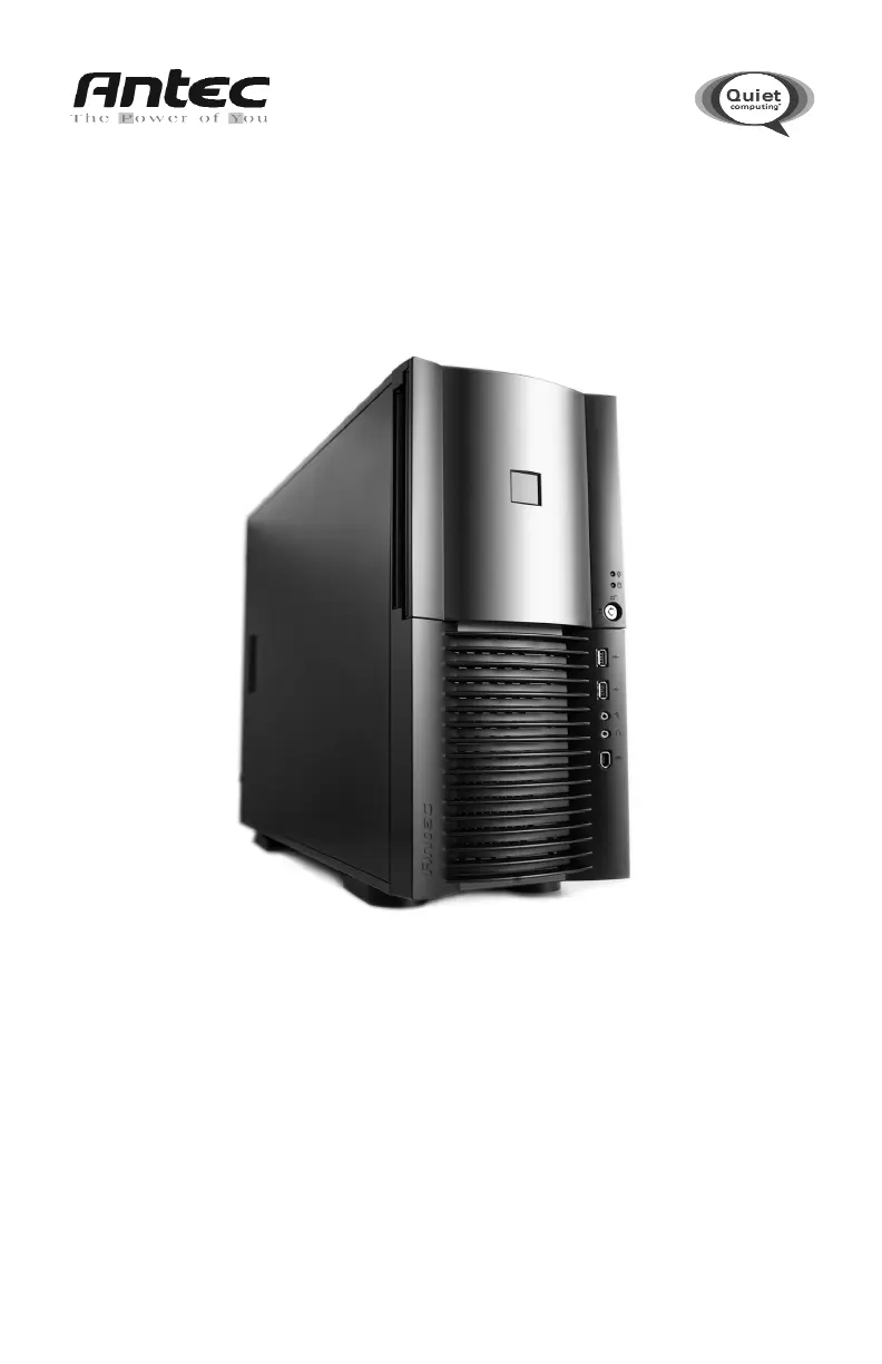
TITAN550
USER’S MANUAL
Product specificaties
| Merk: | Antec |
| Categorie: | Niet gecategoriseerd |
| Model: | TITAN550 |
Heb je hulp nodig?
Als je hulp nodig hebt met Antec TITAN550 stel dan hieronder een vraag en andere gebruikers zullen je antwoorden
Handleiding Niet gecategoriseerd Antec

14 Juli 2026
8 Juli 2026
11 Mei 2026
7 Mei 2026
25 December 2025
23 December 2025
20 Juni 2025
16 Juni 2025
18 April 2025
18 April 2025
Handleiding Niet gecategoriseerd
Nieuwste handleidingen voor Niet gecategoriseerd
3 Augustus 2026
3 Augustus 2026
3 Augustus 2026
3 Augustus 2026
3 Augustus 2026
3 Augustus 2026
3 Augustus 2026
3 Augustus 2026
3 Augustus 2026
3 Augustus 2026