AMX MXR-1001 Handleiding
AMX Niet gecategoriseerd MXR-1001
Bekijk gratis de handleiding van AMX MXR-1001 (2 pagina’s), behorend tot de categorie Niet gecategoriseerd. Deze gids werd als nuttig beoordeeld door 818 mensen en kreeg gemiddeld 4.5 sterren uit 7 reviews. Heb je een vraag over AMX MXR-1001 of wil je andere gebruikers van dit product iets vragen? Stel een vraag
Pagina 1/2
QUICK START GUIDE
MXR-100110.1" Modero X
®
Series G5 Retractable Touch Panel
Overview
The MXR-1001 / 10.1" Modero X
®
Series G5 Retractable Touch Panel mounts beneath the
table so it hides away when not in use.
Installing the MXR-1001
Read these instructions in their entirety before beginning the installation.
This installation requires specific woodworking skills. Only a professional, AMX-qualified
installer should perform this installation. Installation must conform to all local codes. This
product may not be installed by the end-user.
NOTE: Due to the weight of the MXR-1001, this installation requires TWO INSTALLERS.
Required Accessories (Not Included)
•Straight-Cut Router bit: Freud 12-128 or Whiteside 1072 (0.5” or 12mm / 12.7mm OD)
•Guide Bushing: Woodcraft 144693 (.75” or 19 mm OD)
•Bushing Lock Nut: Woodcraft 144696
1) Unbox the MXR-1001 and Remove Packing Materials
1.Carefully remove the MXR-1001 from the shipping box and remove all packing
materials.
2.Be sure to remove the protective foam padding from both the front and the back of the
touch panel.
2) Select a Suitable Location
Ensure that the MXR-1001 will not interfere with the normal use of the work space when
installed, both above and below the mounting surface. For example, ensure that the Motor
chassis does not interfere with the user's legs when seated at the table.
Also, ensure that other devices installed in proximity to the MXR-1001 will not interfere with
the installation and use of the MXR-1001.
Mounting Surface Requirements
Note: Use the included surface extender for surfaces thicker than 2” (50mm). Refer to the
MXR-1001 Hardware Installation Guide for details.
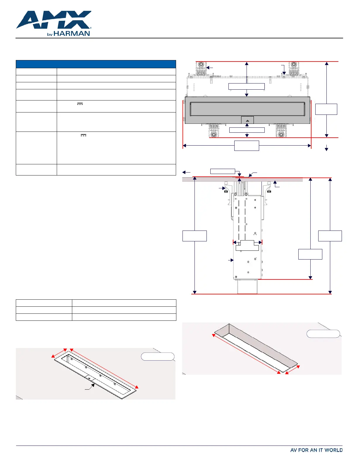
Above-Surface Dimensions
FIG.1 indicates the above-surface dimensions of the MXR-1001, including the Bezel:
Below-Surface Dimensions
FIG.2 provides a top view of an installed MXR-1001, to indicate the area required below the
mounting surface for the chassis and Mounting Clamps:
FIG.3 indicates the below-surface depth requirements for the MXR-1001 (side view):
Hole Cutout Dimensions for the Mounting Surface
Refer to the following table for the dimensions of the actual hole cut out in the mounting
surface, resulting from using the Router Guide and required accessories:
3) Cut the Hole In the Mounting Surface
CAUTION: Always wear safety glasses when operating the router. Failure to comply may result in
eye injury.
Using the specified guide bushing and router bit (not included, see Required Accessories):
1.Use the appropriate Installation Router Guide to mark the edges of the cutout.
2.Carefully cut the opening in the table surface with the router.
•Little clearance exists between the MXR-1001 and the hole cutout in the mounting surface.
Once the MXR-1001 assembly has been installed, the Bezel will cover the cutout hole.
•Carefully align the cutout with the edges or other appropriate features in the table or
mounting surface. If the cutout is misaligned, the installed unit will be misaligned.
•Use a drill and drill bit to make a starting hole within the boundary of the cutout. Use an
appropriate cutting tool to finish the cutout.
MXR-1001 SPECIFICATIONS
DIMENSIONS (HWD) 15.325” x 11.010” x 6.753” (389.25mm x 279.65mm x 171.53mm)
CUTOUT DIMENSIONS10.701” x 1.984” (271.81mm x 50.39 mm)
WEIGHT18.85 lbs (8.55 Kg)
POWER CONSUMPTIONFull-On: 15.6W (in motion) / Full-On (no motion): 7.2W
Sleep: 4.6W, Shut Down 0.12W, Start-Up Inrush Current: 7.1 amps
POWER SUPPLY
PSR2.5 24V external power supply (included), uses 3-pin captive wire
connector to connect to the MXR-1001.
CERTIFICATIONS•FCC Part 15 Class B
•C-Tick CISPR 22 Class B
•CE EN 55022 Class B, EN 55024,
and EN 55032
•IC/CSA
•IEC/EN-60950
•UL 60950-1
•RoHS/WEEE/ErP compliant
INCLUDED
ACCESSORIES
•PSR2.5 24V external power supply (FG423-47)
•Cardstock Installation Cutout Template
•7 Mounting Screws
•4 Mounting Clamps
•1 snap-on cable Ferrite
•1 Mounting Spacer / 4 screws (60-5968-115)
•MXA-CLK, Modero X/S Series Cleaning Kit (FG5968-16)
OPTIONAL
ACCESSORIES
•MX-AC-TMPLT-MXR10, Aluminum Installation Router Guide (FG559-96)
Above Mounting Surface (HWD):9.57" x 10.55" x 4.53" (243mm x 268mm x 115mm)
Below Mounting Surface (HWD):15.37" x 12.04" x 6.78" (391mm x 306mm x 173mm)
Mounting Surface Thickness:Min: 0.5” (12.7mm) / Max: 2.0” (50mm)
FIG. 1 ABOVE-SURFACE DIMENSIONS OF MXR-1001
Bezel
mounting surface
Height above table = 0.079” (2 mm)
2.405” (61.09 mm)
11.142” (283 mm)
FIG. 2 MXR-1001: TOP VIEW, INDICATING AREA REQUIRED BELOW THE MOUNTING SURFACE
FIG. 3 DIMENSIONS OF THE MXR-1001 (SIDE VIEW, BELOW THE MOUNTING SURFACE)
FIG. 4 ABOVE-SURFACE DIMENSIONS OF MXR-1001
Mounting
Clamps (x4)
Motor chassis
Bezel
(above surface)
11.010”
(279.65mm)
6.753”
(171.53mm)
1.209” (30.71mm)
3.147” (79.93mm)
front
(below surface)
mounting surface
15.246”
(387.25mm)
13.315”
(338.20mm)
front
15.325”
(389.25mm)
Motor chassis
4.196”
(106.58mm)
Mounting
Clamps
(x4)
0.079” (2mm)
Bezel (above surface)
mounting surface
10.701” (271.81 mm)
1.984” (50.39 mm)
Product specificaties
| Merk: | AMX |
| Categorie: | Niet gecategoriseerd |
| Model: | MXR-1001 |
Heb je hulp nodig?
Als je hulp nodig hebt met AMX MXR-1001 stel dan hieronder een vraag en andere gebruikers zullen je antwoorden
Handleiding Niet gecategoriseerd AMX

8 Juli 2026
7 Juli 2026
6 Juli 2026
10 Mei 2026
7 Mei 2026
5 Mei 2026
4 Mei 2026
24 November 2025
5 Augustus 2025
5 Augustus 2025
Handleiding Niet gecategoriseerd
Nieuwste handleidingen voor Niet gecategoriseerd
23 Juli 2026
23 Juli 2026
23 Juli 2026
23 Juli 2026
23 Juli 2026
22 Juli 2026
22 Juli 2026
22 Juli 2026
22 Juli 2026
22 Juli 2026