AMX MXD-700-NC Handleiding
AMX Niet gecategoriseerd MXD-700-NC
Bekijk gratis de handleiding van AMX MXD-700-NC (2 pagina’s), behorend tot de categorie Niet gecategoriseerd. Deze gids werd als nuttig beoordeeld door 69 mensen en kreeg gemiddeld 4.7 sterren uit 6 reviews. Heb je een vraag over AMX MXD-700-NC of wil je andere gebruikers van dit product iets vragen? Stel een vraag
Pagina 1/2
QUICK START GUIDE
MXD-700 7" Modero X
®
Series Wall Mount Touch Panel
Overview
The MXD-700 7" Modero X Series
®
Wall Mount Touch Panel features edge-to-edge capacitive
touch glass with multi-touch capabilities as well as advanced technology empowering users to
operate AV equipment seamlessly, while providing the ultimate in audio and video quality. The
MXD-700 is available in Portrait and Landscape layouts:
Product Specifications
For a full listing of product specifications, refer to the X-Series Touch Panels MXD/T-1000,
MXD/T-700 & MXD-430 Instruction Manual (available to view/download from www.amx.com).
Note: The MXD-700-P-NC (FG5968-28) and MXD-700-L-NC (FG5968-29) No Comm touch
panels do not have microphone capability. These otherwise have all of the functionality of the
MXD-700 panels.
MXD-700 Installation
•For more detailed installation instructions including important notes on thermal
concerns with Rack and Wall installations, refer to the X-Series Touch Panels MXD/
T-1000, MXD/T-700 & MXD-430 Instruction Manual (available to view/download from
www.amx.com).
•Detailed specifications drawings for the MXD-700 are available to download from
www.amx.com.
The MXD-700 may be installed directly into a solid surface environment, using either solid
surface screws or the included locking tabs for different mounting options.
Once installed, the MXD-700 is contained within a clear outer housing known as the Backbox
(FIG.2). The Backbox is removed to install it into a wall, or when using the optional Rough-In
Box accessory (FG039-18).
Note: For typical mounting surfaces, such as drywall, use the locking tabs as the primary
method for securing the Backbox to the surface. For thin walls or solid surfaces, use mounting
screws (not included).
Power Via PoE
Power for the MXD-700 is supplied via PoE (Power Over Ethernet), utilizing an AMX-certified,
capacitive touch-compliant PoE injector or other approved AMX PoE power source. The
incoming Ethernet cable should be connected to the RJ45 port on the MXD-700.
Installing the MXD-700 Into a Wall
The MXD-700 comes with a clear plastic Backbox (designed to attach the panel to most
standard wall materials. This Backbox has two locking tabs (one on top and one on bottom) to
help lock the Backbox to the wall. These locking tabs are only extended AFTER the Backbox is
inserted into the wall (FIG.3).
•When installing the Backbox, make sure that the assembly is in the correct position and
in the correct place. Once the locking tabs are extended and locked into place, removing
the Backbox may be difficult without having access to the back of the wall or causing
damage to the wall.
•In order to ensure a stable installation of the MXD-700, the thickness of the wall
material must be a minimum of .50 inches (1.27cm) and a maximum of .875 inches
(2.22cm). The mounting surface should also be smooth and flat.
Installing the Backbox
For best results, use the included Installation Template (68-5968-04) to ensure proper
placement. The template is marked on one side with directions for both landscape and portrait
installations to ensure that the touch panel and Backbox are properly aligned.
WARNING: Using the Installation Template to select the final placement of the Backbox is highly
recommended. The outside edges of the template are the same dimensions as the touch panel,
which allows you to troubleshoot possible conflicts with wall edges, doors, and other potential
obstacles.
1.Prepare the area by removing any screws or nails from the drywall before beginning the
cutout process.
2.After ensuring proper placement, cut out the mounting surface for the Backbox, using
the (included) Installation Template as a guide.
CAUTION: Making sure the actual cutout opening is slightly smaller than the provided
dimensions is highly recommended. This provides a margin of error if the opening needs to
be expanded. Too little wall material removed is always better than too much.
3.Thread the incoming Ethernet cable through the surface opening (FIG.4).
Leave enough slack in the wiring to accommodate any re-positioning of the panel.
4.Remove the Backbox knockouts and thread the incoming wiring through the knockout
holes.
5.Thread the incoming cables from the mounting surface opening and through the
knockouts.
6.Push the Backbox into the mounting surface. Insure that the locking tabs lie flush
against the Backbox and that the Backbox goes freely into the opening.
7.Extend the locking tabs on the sides of the Backbox by tightening the screws inside the
box until snug. Apply enough pressure to the screw head to keep the box flush with the
wall: this ensures that the locking tabs will tighten up against the inside of the wall. The
Backbox is clear to allow visual confirmation that the tabs have been extended and are
gripping the wall, as well as in assisting with removal if necessary.
Note: The maximum recommended torque to screw in the locking tabs on the Backbox is 5
IN-LB [56 N-CM]. Applying excessive torque while tightening the tab screws, such as with
powered screwdrivers, can strip out the locking tabs or damage the Backbox.
8.For additional strength, #4 mounting screws (not included) may be secured via
mounting holes located at the left and right sides of the MXD-700 (FIG.4). In order to
prevent damage to the touch panel, make sure that these are flush with the Backbox.
PortraitMXD-700-PFG5968-08
LandscapeMXD-700-LFG5968-14
FIG. 1 MXD-700-P/L WALL MOUNT (PORTRAIT AND LANDSCAPE)
MXD-700 SPECIFICATIONS
Dimensions (HWD)•Landscape: 4 13/16" x 7 5/16" x 2 1/2" (122mm x 186mm x 63mm)
•Portrait: 7 5/16" x 4 13/16" x 2 1/2" (186mm x 122mm x 63mm)
Weight1.4 lbs (0.64 Kg)
Power Consumption•Full-On: 8W
•Standby: 3.2W
•Shutdown: 1W
•Start-Up Inrush Current: Not applicable due to PoE standard
External Power
Supply Required
Optimal performance requires use of one of the following AMX PoE power
supplies (not included):
•PS-POE-AF-TC, PoE Injector, 802.3AF Compliant (FG423-83)
•NXA-ENET8-2POE, Gigabit PoE Ethernet Switch (FG2178-63)
Certifications•UL 60950-1
•FCC Part 15 Class B
•C-Tick CISPR 22 Class B
•CE EN 55022, EN 55024 and EN 60950-1
•IEC 60950-1
•IC
•IEC/EN-60950
•RoHS/WEEE compliant
Environmental•Temperature (Operating): 32° F to 104° F (0°C to 40°C)
•Temperature (Storage): 4° F to 140° F (-20°C to 60°C)
•Humidity (Operating): 20% to 85% RH
•Humidity (Storage): 5% to 85% RH
•Power ("Heat") Dissipation:
On: 18.5 BTU/hr
Standby: 10.6 BTU/hr
Included
Accessories
•MXA-USB-C, USB Port Cover Kit (FG5968-18)
•MXA-CLK, Modero X/S Series Cleaning Kit (FG5968-16)
•MXD-700 Installation Template
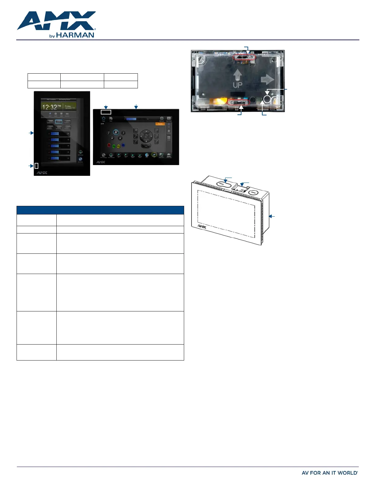
Sleep ButtonNFC Sensor
Sleep
NFC
Button
MXD-700-L
MXD-700-P
Sensor
FIG. 2 MXD-700 BACKBOX (REAR VIEW)
FIG. 3 MXD-700 (LANDSCAPE)
Locking tab
Locking tab
RJ45 cable clip
RJ45 Cable/Port
Backbox
Backbox knockouts (X4)
Locking tabs (X2)
Product specificaties
| Merk: | AMX |
| Categorie: | Niet gecategoriseerd |
| Model: | MXD-700-NC |
Heb je hulp nodig?
Als je hulp nodig hebt met AMX MXD-700-NC stel dan hieronder een vraag en andere gebruikers zullen je antwoorden
Handleiding Niet gecategoriseerd AMX

10 Mei 2026
7 Mei 2026
5 Mei 2026
4 Mei 2026
24 November 2025
5 Augustus 2025
5 Augustus 2025
4 Augustus 2025
4 Augustus 2025
4 Augustus 2025
Handleiding Niet gecategoriseerd
Nieuwste handleidingen voor Niet gecategoriseerd
8 Juni 2026
8 Juni 2026
8 Juni 2026
8 Juni 2026
8 Juni 2026
8 Juni 2026
8 Juni 2026
8 Juni 2026
8 Juni 2026
8 Juni 2026