AMX MX-AC-TMPLT-MXR10 Handleiding
AMX Niet gecategoriseerd MX-AC-TMPLT-MXR10
Bekijk gratis de handleiding van AMX MX-AC-TMPLT-MXR10 (2 pagina’s), behorend tot de categorie Niet gecategoriseerd. Deze gids werd als nuttig beoordeeld door 103 mensen en kreeg gemiddeld 4.3 sterren uit 5 reviews. Heb je een vraag over AMX MX-AC-TMPLT-MXR10 of wil je andere gebruikers van dit product iets vragen? Stel een vraag
Pagina 1/2
QUICK START GUIDE
MX-AC-TMPLT-MXR10Installation Router Guide for MXR-1001 Retractable Touch Panel
Overview
The MX-AC-TMPLT-MXR10 HydraPort
®
Installation Router Guide for MXR-1001
(FG5968-90) provides an easy and accurate method of creating a hole in the
installation surface for the MXR-1001 10.1" Modero X
®
Series G5 Retractable Touch
Panel (FIG.1):
Use the MX-AC-TMPLT-MXR10 along with the required accessories to create the hole in
the mounting surface to install the MXR-1001.
CAUTION: Only a professional, AMX-qualified installer should perform the installation of
AMX Retractable Touch Panels. Installation must conform to all local codes. These
products may not be installed by the end-user.
The installation of AMX Retractable Touch Panels requires specific woodworking skills.
This installation should be performed by an experienced person, comfortable with these
types of woodworking operations. Improper installation may result in damage to the
mounting surface. Refer to the MXR-1001 Installation Guide for details instructions on
mounting the MXR-1001.
Selecting a Suitable Location for the MXR-1001
Care must be taken to ensure that the MXR-1001 does not interfere with the normal
use of the work space. For example, on a table or work surface, ensure that the system
does not interfere with the user's legs when they are seated at the table.
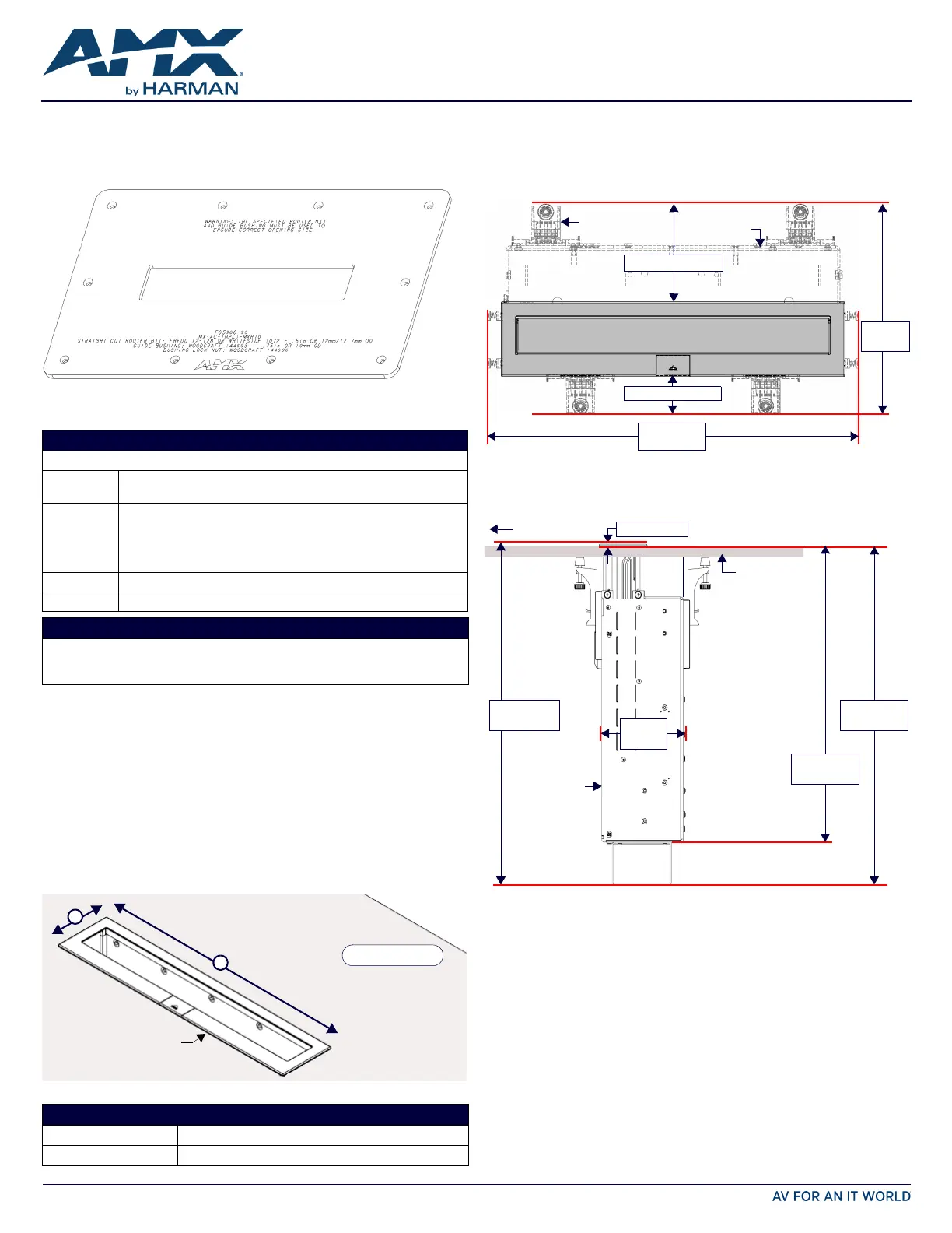
Above-Surface Dimensions
FIG.2 indicates the above-surface dimensions of the MXR-1001, including the bezel:
Below-Surface Dimensions of the MXR-1001
When locating the position of the cutout, it is important to understand the area
required beneath the mounting surface by the MXR-1001 assembly when installed. Be
sure to allow sufficient room for the aluminum chassis as well as the mounting clamps.
FIG.3 provides a top view of an installed MXR-1001, to indicate the area required below
the mounting surface for the chassis and mounting clamps:
Note: Be sure to allow sufficient room (at least a few inches) to access the two screws
that attach each side of the MXR-1001 bezel to the chassis.
FIG.4 indicates the below-surface depth requirements for the MXR-1001 (side view):
•MXR-1001 requires a mounting surface thickness between 0.5” (13 mm) to
2” (51 mm).
•The MXR-1001 will have a total depth of 15.366" (390.248 mm).
FIG. 1
MX-AC-TMPLT-MXR10 ROUTER GUIDE
MX-AC-TMPLT-MXR10 SPECIFICATIONS
Dimensions:
Outside
Dimensions:
•Horizontal: 18.897” (480.0 mm)
•Vertical: 11.614” (295.0 mm)
Cutout
Dimensions:
•Horizontal: 10.951” (278.16 mm)
•Vertical: 2.233” (56.74 mm)
Refer to the Hole Cutout Dimensions for the Mounting Surface section on
page 2 for the size of the actual hole cut out in the mounting surface,
resulting from using the Router Guide and required accessories:
Thickness:0.25” (6.35 mm)
Weight:4.96 lbs (2.25 kg)
REQUIRED ACCESSORIES (NOT INCLUDED)
•Straight-Cut Router bit: Freud 12-128 or Whiteside 1072 (0.5” or 12mm / 12.7mm OD)
•Guide Bushing: Woodcraft 144693 (.75” or 19 mm OD)
•Bushing Lock Nut (Woodcraft 144696)
FIG. 2 ABOVE-SURFACE DIMENSIONS OF MXR-1001
DIMENSIONS OF MXR-1001
Length of “A”:
2.405” (61.09 mm)
Length of “
B”:
11.142” (283.00 mm)
MXR-1001 (Bezel)
A
B
Mounting Surface
Height above table =
0.12” (3 mm)
FIG. 3 MXR-1001: TOP VIEW, INDICATING AREA REQUIRED BELOW THE MOUNTING SURFACE
FIG. 4 DIMENSIONS OF THE MXR-1001 (SIDE VIEW, BELOW THE MOUNTING SURFACE)
Mounting
Clamps (x4)
MXR-1001
chassis
Bezel with pushbutton and door
(above table)
12.039”
(305.79mm)
6.781”
(172.23mm)
1.219” (30.96mm)
3.157” (80.18mm)
0.12” (3 mm)
Mounting Surface
15.246”
(387.25 mm)
13.315”
(338.20 mm)
front
15.366”
(390.25 mm)
4.150”
(105.41 mm)
MXR-1001
chassis
Product specificaties
| Merk: | AMX |
| Categorie: | Niet gecategoriseerd |
| Model: | MX-AC-TMPLT-MXR10 |
Heb je hulp nodig?
Als je hulp nodig hebt met AMX MX-AC-TMPLT-MXR10 stel dan hieronder een vraag en andere gebruikers zullen je antwoorden
Handleiding Niet gecategoriseerd AMX

10 Mei 2026
7 Mei 2026
5 Mei 2026
4 Mei 2026
24 November 2025
5 Augustus 2025
5 Augustus 2025
4 Augustus 2025
4 Augustus 2025
4 Augustus 2025
Handleiding Niet gecategoriseerd
Nieuwste handleidingen voor Niet gecategoriseerd
8 Juni 2026
8 Juni 2026
8 Juni 2026
8 Juni 2026
8 Juni 2026
8 Juni 2026
8 Juni 2026
8 Juni 2026
8 Juni 2026
8 Juni 2026